

Question: 4 - 7 . Graphically position the links for the shearing mechanism in the configuration shown in Figure P 4 . 7 . Then reposition
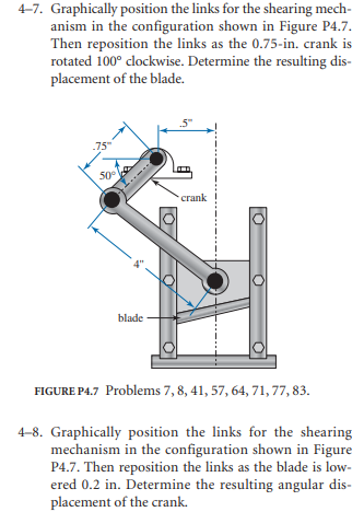
Graphically position the links for the shearing mechanism in the configuration shown in Figure P Then reposition the links as the mathrmin crank is rotated circ clockwise. Determine the resulting displacement of the blade.
FIGURE P Problems
Graphically position the links for the shearing mechanism in the configuration shown in Figure P Then reposition the links as the blade is lowered in Determine the resulting angular displacement of the crank.
Step by Step Solution
There are 3 Steps involved in it
1 Expert Approved Answer
Step: 1 Unlock

Question Has Been Solved by an Expert!
Get step-by-step solutions from verified subject matter experts
Step: 2 Unlock
Step: 3 Unlock