

Question: help me please answer this asap please draw the kinematic diagram based on the information above. POSITION AND DISPLACEMENT ANALYSIS (GRAPHICAL METHOD) Graphically determine the
help me please answer this asap
please draw the kinematic diagram based on the information above.
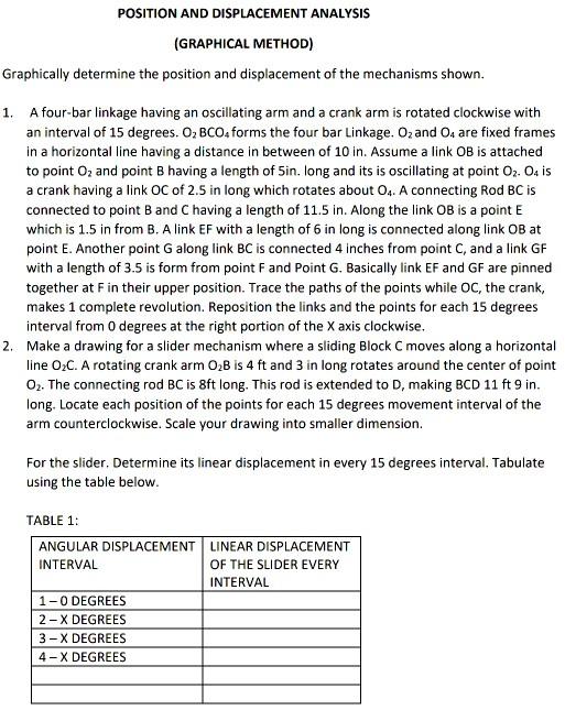
POSITION AND DISPLACEMENT ANALYSIS (GRAPHICAL METHOD) Graphically determine the position and displacement of the mechanisms shown. 1. A four-bar linkage having an oscillating arm and a crank arm is rotated clockwise with an interval of 15 degrees. O, BCO forms the four bar Linkage. Ozand 04 are fixed frames in a horizontal line having a distance in between of 10 in. Assume a link OB is attached to point O2 and point B having a length of Sin. long and its is oscillating at point 02. Od is a crank having a link OC of 2.5 in long which rotates about 04. A connecting Rod BC is connected to point B and Chaving a length of 11.5 in. Along the link OB is a point E which is 1.5 in from B. A link EF with a length of 6 in long is connected along link OB at point E. Another point G along link BC is connected 4 inches from point C, and a link GF with a length of 3.5 is form from point F and Point G. Basically link EF and GF are pinned together at F in their upper position. Trace the paths of the points while OC, the crank, makes 1 complete revolution. Reposition the links and the points for each 15 degrees interval from 0 degrees at the right portion of the X axis clockwise. 2. Make a drawing for a slider mechanism where a sliding Block C moves along a horizontal line O.C. A rotating crank arm OB is 4 ft and 3 in long rotates around the center of point O2. The connecting rod BC is 8ft long. This rod is extended to D, making BCD 11 ft 9 in. long. Locate each position of the points for each 15 degrees movement interval of the arm counterclockwise. Scale your drawing into smaller dimension. For the slider. Determine its linear displacement in every 15 degrees interval. Tabulate using the table below. TABLE 1: ANGULAR DISPLACEMENT LINEAR DISPLACEMENT INTERVAL OF THE SLIDER EVERY INTERVAL 1-O DEGREES 2-X DEGREES 3-X DEGREES 4-X DEGREES POSITION AND DISPLACEMENT ANALYSIS (GRAPHICAL METHOD) Graphically determine the position and displacement of the mechanisms shown. 1. A four-bar linkage having an oscillating arm and a crank arm is rotated clockwise with an interval of 15 degrees. O, BCO forms the four bar Linkage. Ozand 04 are fixed frames in a horizontal line having a distance in between of 10 in. Assume a link OB is attached to point O2 and point B having a length of Sin. long and its is oscillating at point 02. Od is a crank having a link OC of 2.5 in long which rotates about 04. A connecting Rod BC is connected to point B and Chaving a length of 11.5 in. Along the link OB is a point E which is 1.5 in from B. A link EF with a length of 6 in long is connected along link OB at point E. Another point G along link BC is connected 4 inches from point C, and a link GF with a length of 3.5 is form from point F and Point G. Basically link EF and GF are pinned together at F in their upper position. Trace the paths of the points while OC, the crank, makes 1 complete revolution. Reposition the links and the points for each 15 degrees interval from 0 degrees at the right portion of the X axis clockwise. 2. Make a drawing for a slider mechanism where a sliding Block C moves along a horizontal line O.C. A rotating crank arm OB is 4 ft and 3 in long rotates around the center of point O2. The connecting rod BC is 8ft long. This rod is extended to D, making BCD 11 ft 9 in. long. Locate each position of the points for each 15 degrees movement interval of the arm counterclockwise. Scale your drawing into smaller dimension. For the slider. Determine its linear displacement in every 15 degrees interval. Tabulate using the table below. TABLE 1: ANGULAR DISPLACEMENT LINEAR DISPLACEMENT INTERVAL OF THE SLIDER EVERY INTERVAL 1-O DEGREES 2-X DEGREES 3-X DEGREES 4-X DEGREES
Step by Step Solution
There are 3 Steps involved in it

Get step-by-step solutions from verified subject matter experts