

Question: 4 . A coupled inductor circuit is shown below. I guie IJ . 0 L For rrod. 1 9 . 1 2 . a .
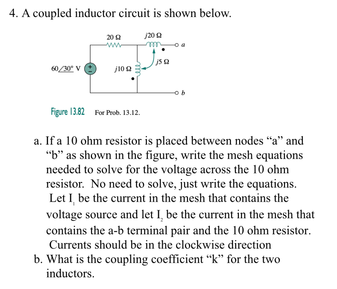
A coupled inductor circuit is shown below.
I guie IJL For rrod.
a If a ohm resistor is placed between nodes a and b as shown in the figure, write the mesh equations needed to solve for the voltage across the ohm resistor. No need to solve, just write the equations. Let I be the current in the mesh that contains the voltage source and let I be the current in the mesh that contains the ab terminal pair and the ohm resistor. Currents should be in the clockwise direction
b What is the coupling coefficient k for the two inductors.
Step by Step Solution
There are 3 Steps involved in it
1 Expert Approved Answer
Step: 1 Unlock

Question Has Been Solved by an Expert!
Get step-by-step solutions from verified subject matter experts
Step: 2 Unlock
Step: 3 Unlock