

Question: 4- An 8 bit CPU having 64kBytes addressing capability will be connected to a memory block that contains 1 piece of 27C256 EPROM, 1
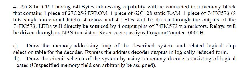
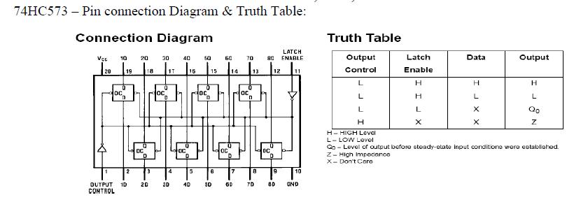
4- An 8 bit CPU having 64kBytes addressing capability will be connected to a memory block that contains 1 piece of 27C256 EPROM, 1 piece of 62C128 static RAM, 1 piece of 74HC573 (8 bits single directional latch). 4 relays and 4 LEDs will be driven through the outputs of the 74HC573. LEDs will directly be sourced by 4 output pins of 74HC573 via resistors. Relays will be driven through an NPN transistor. Reset vector assigns ProgramCounter=0000H. a) Draw the memory-addressing map of the described system and related logical chip selection table for the decoder. Express the address decoder outputs in logically reduced form. b) Draw the circuit schema of the system by using a memory decoder consisting of logical gates (Unspecified memory field can arbitrarily be assigned). 74HC573 - Pin connection Diagram & Truth Table: Connection Diagram Vcc 10 20 30 19 oc 2 OUTPUT 10 CONTROL OC 18 3 20 0 1T 4 3D 40 15 D 5 40 50 loc 0 15 6 50 60 OC 14 D 7 60 70 oc 13 0 8 7D LATCH 80 ENABLE 12 Q DC 0 9 11 10 END Truth Table Output Control Latch Enable H H L X Z- High Impedance X- Don't Care Data H L L L H H-HIGH Level L- LOW Level Qp-Level of output before steady-state input conditions were established. JXX Output L H L Qo Z
Step by Step Solution
There are 3 Steps involved in it

Get step-by-step solutions from verified subject matter experts