

Question: 4 . Consider the pipe fitting shown in the figure below. Water is flowing through the fitting, and pressure measurements indicate that the pressure at
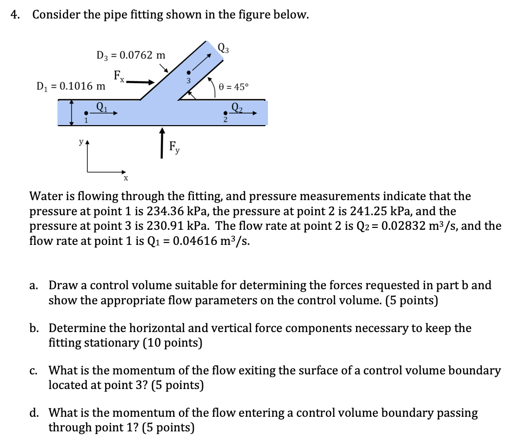
Consider the pipe fitting shown in the figure below.
Water is flowing through the fitting, and pressure measurements indicate that the pressure at point is kPa the pressure at point is kPa and the pressure at point is kPa The flow rate at point is mathrmQmathrm~mmathrms and the flow rate at point is mathrmQmathrm~mmathrms
a Draw a control volume suitable for determining the forces requested in part b and show the appropriate flow parameters on the control volume. points
b Determine the horizontal and vertical force components necessary to keep the fitting stationary points
c What is the momentum of the flow exiting the surface of a control volume boundary located at point points
d What is the momentum of the flow entering a control volume boundary passing through point points
Step by Step Solution
There are 3 Steps involved in it
1 Expert Approved Answer
Step: 1 Unlock

Question Has Been Solved by an Expert!
Get step-by-step solutions from verified subject matter experts
Step: 2 Unlock
Step: 3 Unlock