

Question: 4. The figure Q4 below shows a halfwave rectifier circuit. a) Sketch the output vo and determine the dc level of the output for
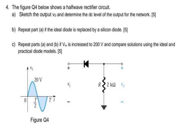
4. The figure Q4 below shows a halfwave rectifier circuit. a) Sketch the output vo and determine the dc level of the output for the network. [5] b) Repeat part (a) if the ideal diode is replaced by a silicon diode. [5] c) Repeat parts (a) and (b) if Vm is increased to 200 V and compare solutions using the ideal and practical diode models. [5] 0 V 20 V 72 Ti Figure Q4 R2kQ
Step by Step Solution
★★★★★
3.45 Rating (165 Votes )
There are 3 Steps involved in it
1 Expert Approved Answer
Step: 1 Unlock

a output voltage Vo M b V 201 ... View full answer
Question Has Been Solved by an Expert!
Get step-by-step solutions from verified subject matter experts
Step: 2 Unlock
Step: 3 Unlock