

Question: Figure 1 is a halfwave rectifier circuit employing a silicon diode with a forward on- potential of 0.7 V. vo Figure 1 Given Vs
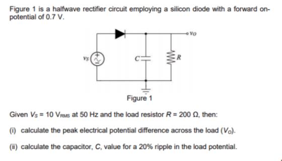
Figure 1 is a halfwave rectifier circuit employing a silicon diode with a forward on- potential of 0.7 V. vo Figure 1 Given Vs = 10 VRas at 50 Hz and the load resistor R = 200 0, then: () calculate the peak electrical potential difference across the load (Vo). (i) calculate the capacitor, C, value for a 20% ripple in the load potential.
Step by Step Solution
There are 3 Steps involved in it
1 Expert Approved Answer
Step: 1 Unlock

Question Has Been Solved by an Expert!
Get step-by-step solutions from verified subject matter experts
Step: 2 Unlock
Step: 3 Unlock
Document Format (2 attachments)
635df29b2f542_180207.pdf
180 KBs PDF File
635df29b2f542_180207.docx
120 KBs Word File