

Question: 6. Consider a bike crank FEA simulation as shown in Figure 8, where we apply a load (F) of 500 N at the pedal
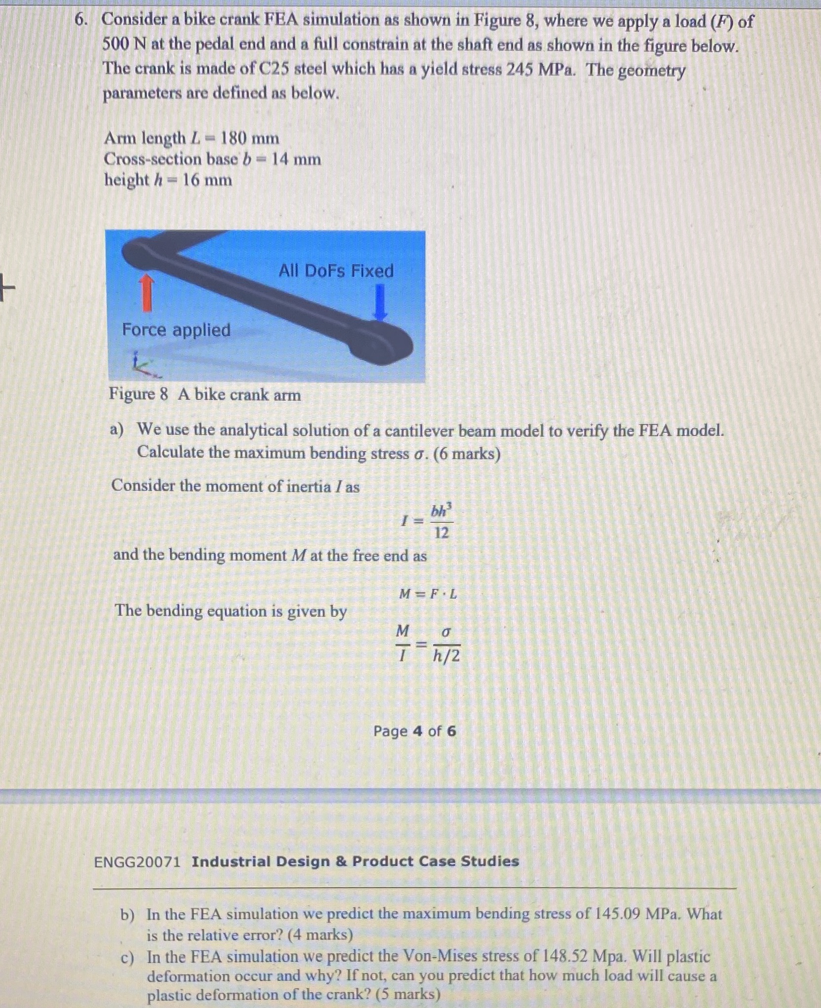
6. Consider a bike crank FEA simulation as shown in Figure 8, where we apply a load (F) of 500 N at the pedal end and a full constrain at the shaft end as shown in the figure below. The crank is made of C25 steel which has a yield stress 245 MPa. The geometry parameters are defined as below. Arm length L 180 mm Cross-section base b = 14 mm height h 16 mm 1 Force applied All DoFs Fixed Figure 8 A bike crank arm a) We use the analytical solution of a cantilever beam model to verify the FEA model. Calculate the maximum bending stress . (6 marks) Consider the moment of inertia I as and the bending moment M at the free end as The bending equation is given by M=F.L M bh 12 II D Th/2 Page 4 of 6 ENGG20071 Industrial Design & Product Case Studies b) In the FEA simulation we predict the maximum bending stress of 145.09 MPa. What is the relative error? (4 marks) c) In the FEA simulation we predict the Von-Mises stress of 148.52 Mpa. Will plastic deformation occur and why? If not, can you predict that how much load will cause a plastic deformation of the crank? (5 marks)
Step by Step Solution
There are 3 Steps involved in it

Get step-by-step solutions from verified subject matter experts