

Question: 6.8 An RLC circuit with a parallel bypass resistor (Problems 3.10 and 5.11) is shown in Fig. P6.8. At time t 0 the circuit has
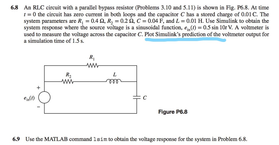
6.8 An RLC circuit with a parallel bypass resistor (Problems 3.10 and 5.11) is shown in Fig. P6.8. At time t 0 the circuit has zero current in both loops and the capacitor C has a stored charge of 0.01 C. The system parameters are R1 = 0.4 ?, R2-0.2 ?, C = 0.04 F, and L = 0.01 H. Use Simulink to obtain the system response where the source voltage is a sinusoidal function, ein(t) -0.5 sin 10t V. A voltmeter is used to measure the voltage across the capacitor C. Plot Simulink's prediction of the voltmeter output for a simulation time of 1.5 s R1 R2 in Figure P6.8 6.9 Use the MATLAB command 1sim to obtain the voltage response for the system in Problem 6.8
Step by Step Solution
There are 3 Steps involved in it

Get step-by-step solutions from verified subject matter experts