

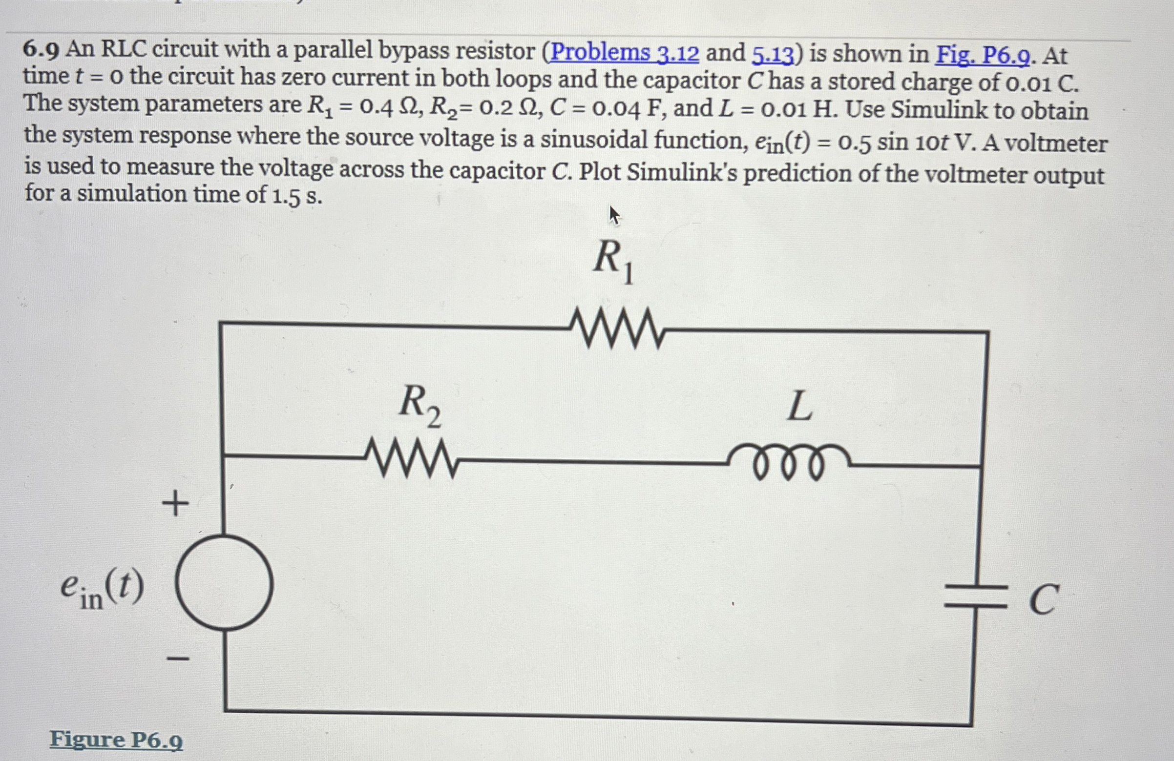
Question: 6 . 9 An RLC circuit with a parallel bypass resistor ( Problems 3 . 1 2 and 5 . 1 3 ) is shown
An RLC circuit with a parallel bypass resistor Problems and is shown in Fig. P At time the circuit has zero current in both loops and the capacitor has a stored charge of C The system parameters are and Use Simulink to obtain the system response where the source voltage is a sinusoidal function, A voltmeter is used to measure the voltage across the capacitor Plot Simulink's prediction of the voltmeter output for a simulation time of s
Wh
Figure P
Step by Step Solution
There are 3 Steps involved in it
1 Expert Approved Answer
Step: 1 Unlock

Question Has Been Solved by an Expert!
Get step-by-step solutions from verified subject matter experts
Step: 2 Unlock
Step: 3 Unlock