

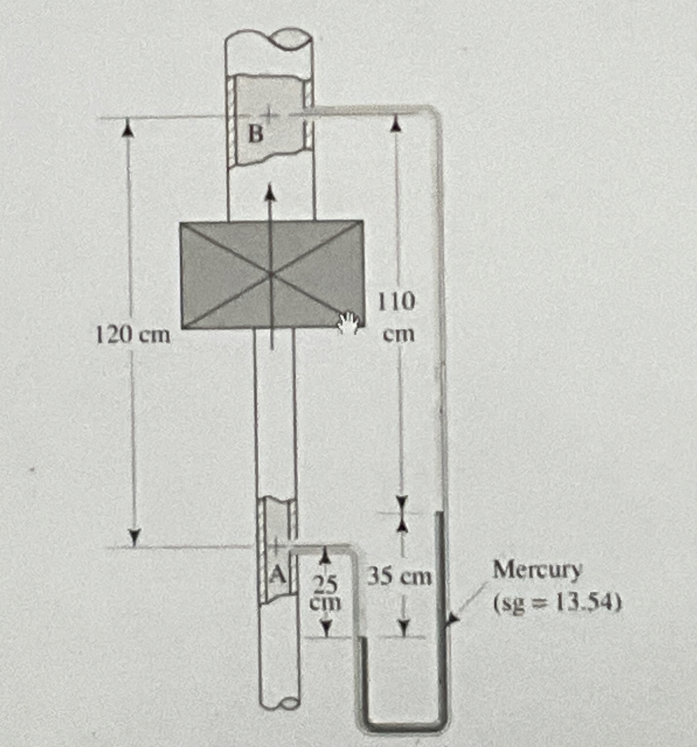
Question: 7 . 5 Figure 7 . 1 4 shows a setup to determine the energy loss due to a certain piece of apparatus. The inlet
Figure shows a setup to determine the energy loss due to a certain piece of apparatus. The inlet is through a in Schedule pipe and the outlet is a in Schedule pipe. Calculate the energy loss between points A and if water is flowing upward at The gage fluid is mercury
Step by Step Solution
There are 3 Steps involved in it
1 Expert Approved Answer
Step: 1 Unlock

Question Has Been Solved by an Expert!
Get step-by-step solutions from verified subject matter experts
Step: 2 Unlock
Step: 3 Unlock