

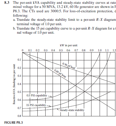
Question: 8 . 3 The per - unit kVA capability and steady - state stability curves at rate minal voltage for a ( 5 0
The perunit kVA capability and steadystate stability curves at rate minal voltage for a mathrmMVAmathrmkVmathrm~Hz generator are shown in F P The CTs used are : For lossofexcitation protection, following:
a Translate the steadystate stability limit to a perunit RX diagram terminal voltage of per unit.
b Translate the psi capability curve to a perunit RX diagram for a nal voltage of per unit.
FIGURE P c With these limits plotted on an RX diagram, draw a distance relay offset mho circle to provide protection for low or loss of excitation on this machine.
d For the relay mho circle selected in part c determine the perunit offset distance of the circle center from the RX origin and the perunit circle radius. Translate these values to relay ohms for setting a lossofexcitation relay, Rcdot R
Step by Step Solution
There are 3 Steps involved in it
1 Expert Approved Answer
Step: 1 Unlock

Question Has Been Solved by an Expert!
Get step-by-step solutions from verified subject matter experts
Step: 2 Unlock
Step: 3 Unlock