

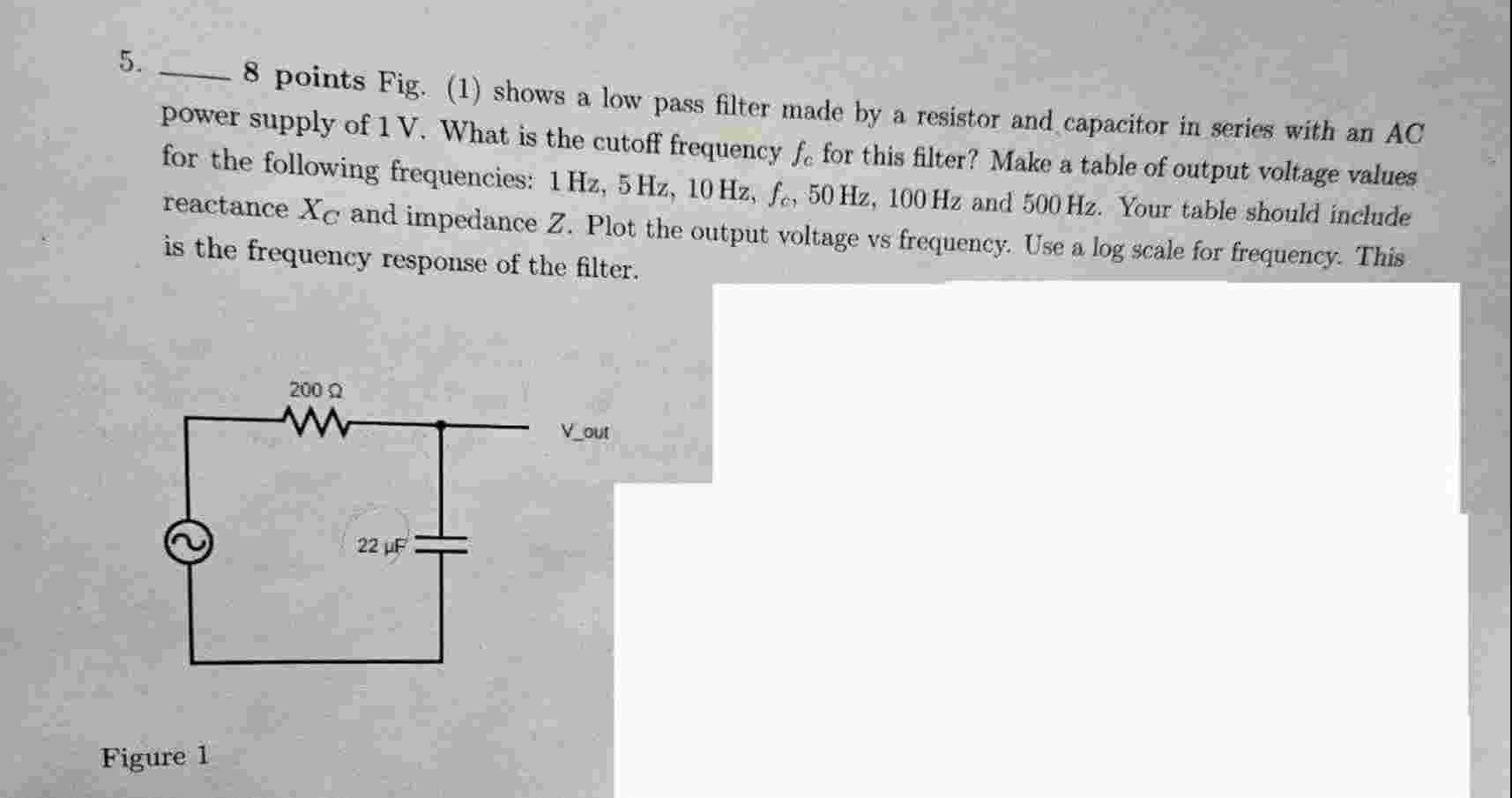
Question: 8 points Fig. ( 1 ) shows a low pass filter made by a resistor and capacitor in series with an AC power supply of
points Fig. shows a low pass filter made by a resistor and capacitor in series with an AC
power supply of V What is the cutoff frequency fc for this filter? Make a table of output voltage values
for the following frequencies: HzHzHzfcHzHz and Hz Your table should include
reactance xC and impedance Z Plot the output voltage vs frequency. Use a log scale for frequency. This
is the frequency response of the filter. Fig. shows a high pass filter. What is the cutoff frequency for this filter?
Vout r and w
Figure
Similar to lenses, filters can be combined in which the output of the first stage is the input to the second stage. Fig. shows the low pass filter followed by the high pass filter. Since fCL P FfCA P F there will be a narrow band that passes through both filters. This is a bandpass filter. For each frequency previously listed, use the output voltage of the LPF to find the output voltage of the second stage of the bandpass filter. Plot the frequency response.
Figure
Step by Step Solution
There are 3 Steps involved in it
1 Expert Approved Answer
Step: 1 Unlock

Question Has Been Solved by an Expert!
Get step-by-step solutions from verified subject matter experts
Step: 2 Unlock
Step: 3 Unlock