

Question: 8-5. Consider the pressure control system shown in Fig. P8-1. The pressure in the tank can be described by F(s)P(s)=(0.15s+1)(0.8s+1)0.4,psi/scfm The valve can be described
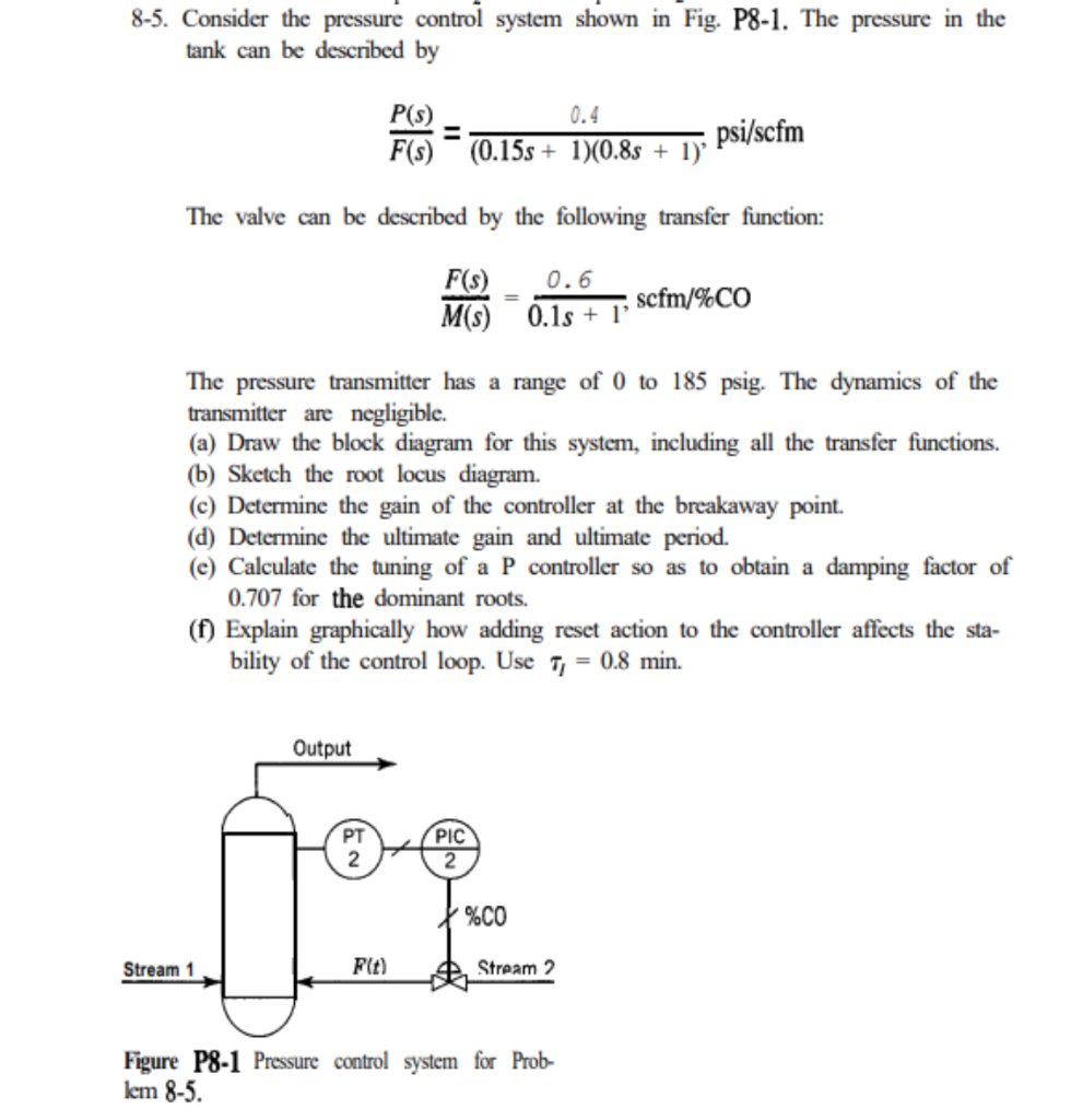
8-5. Consider the pressure control system shown in Fig. P8-1. The pressure in the tank can be described by F(s)P(s)=(0.15s+1)(0.8s+1)0.4,psi/scfm The valve can be described by the following transfer function: M(s)F(s)=0.1s+10.6,scfm/%CO The pressure transmitter has a range of 0 to 185 psig. The dynamics of the transmitter are negligible. (a) Draw the block diagram for this system, including all the transfer functions. (b) Sketch the root locus diagram. (c) Determine the gain of the controller at the breakaway point. (d) Determine the ultimate gain and ultimate period. (e) Calculate the tuning of a P controller so as to obtain a damping factor of 0.707 for the dominant roots. (f) Explain graphically how adding reset action to the controller affects the stability of the control loop. Use I=0.8min. Figure P8-1 Pressure control system for Problem85
Step by Step Solution
There are 3 Steps involved in it

Get step-by-step solutions from verified subject matter experts