

Question: 9 . 4 5 . Assume that the torque output diagram of Fig. 9 . 7 7 is for the first cylinder of a two
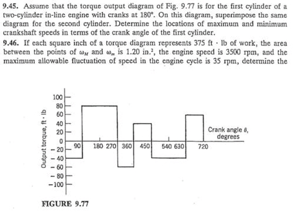
Assume that the torque output diagram of Fig. is for the first cylinder of a
twocylinder inline engine with cranks at On this diagram, superimpose the same
diagram for the second cylinder. Determine the locations of maximum and minimum
crankshaft speeds in terms of the crank angle of the first cylinder.
If each square inch of a torque diagram represents of work, the area
between the points of and is the engine speed is rpm and the
maximum allowable fluctuation of speed in the engine cycle is rpm determine the
FIGURE
Step by Step Solution
There are 3 Steps involved in it
1 Expert Approved Answer
Step: 1 Unlock

Question Has Been Solved by an Expert!
Get step-by-step solutions from verified subject matter experts
Step: 2 Unlock
Step: 3 Unlock