

Question: 9- The block diagram shown below represents the hardware that implements the following microoperations (abc'+ abc'): R1 R2. (abc+abc): R1 R1+ R2 R1 Complementer 0
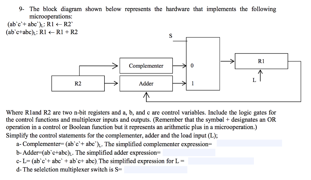
9- The block diagram shown below represents the hardware that implements the following microoperations (abc'+ abc'): R1 R2. (abc+abc): R1 R1+ R2 R1 Complementer 0 R2 Adder Where Rland R2 are two n-bit registers and a, b, and c are control variables. Include the logic gates for the control functions and multiplexer inputs and outputs. (Remember that the symbol + designates an OR operation in a control or Boolean function but it represents an arithmetic plus in a microoperation.) Simplify the control statements for the complementer, adder and the load input (L); a-Complementer= (abc+ abc')L. The simplified complementer expression- b-Adder(abc+abc)L. The simplified adder expression= c-L= (abc'+ abc' + abe+ abc) The simplified expression for L = d-The selection multiplexer switch is S
Step by Step Solution
There are 3 Steps involved in it

Get step-by-step solutions from verified subject matter experts