

Question: a . 8 0 kN 8 0 kN - 2 0 2 0 0 - 4 . The given I - beam shown below is
a
kN
kN
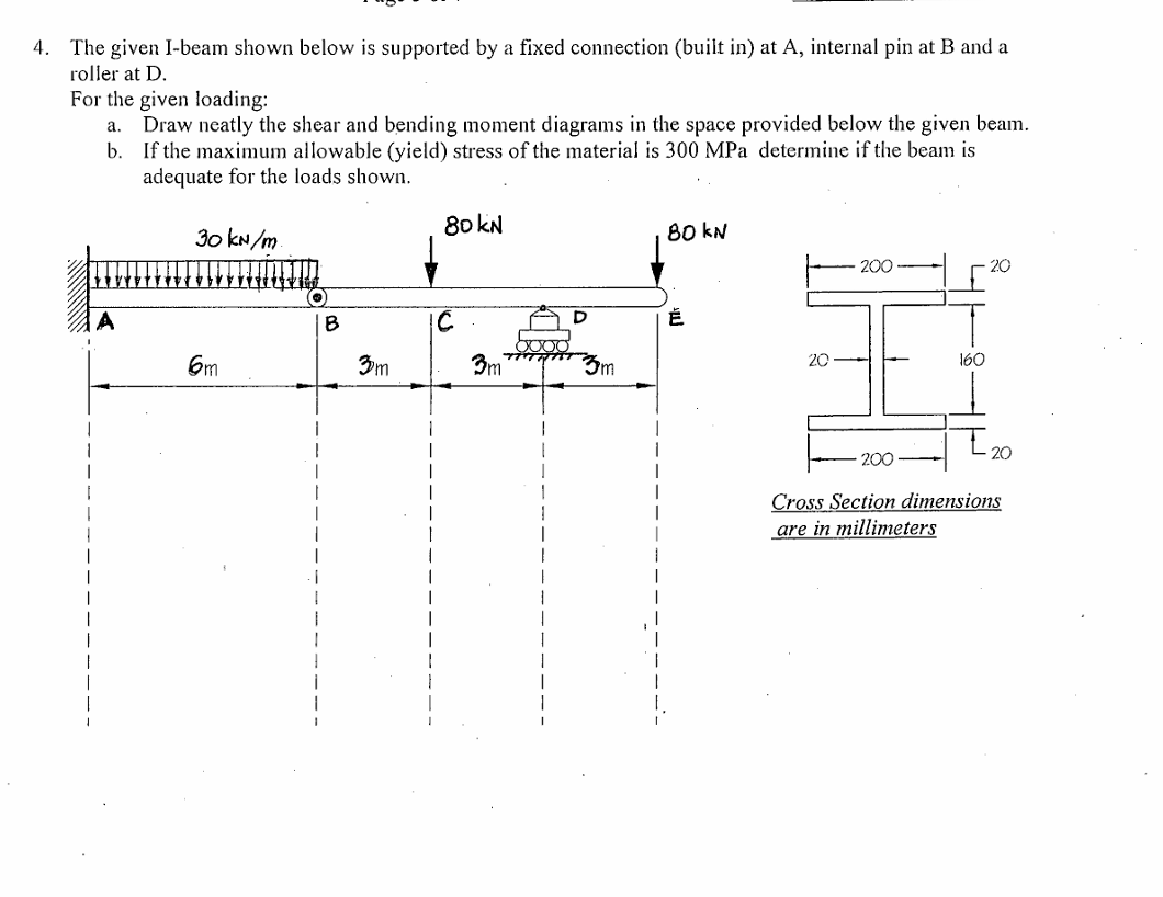
The given Ibeam shown below is supported by a fixed connection built in at A internal pin at B and a
roller at D
For the given loading:
Draw neatly the shear and bending moment diagrams in the space provided below the given beam.
b If the maximum allowable yield stress of the material is MPa determine if the beam is
adequate for the loads shown.
kNm
A
O
B
C
D
m
m
m
C
Cross Section dimensions
are in millimeters
The given Ibeam shown below is supported by a fixed connection built in at A internal pin at B and a roller at D
For the given loading:
a Draw neatly the shear and bending moment diagrams in the space provided below the given beam.
b If the maximum allowable yield stress of the material is MPa determine if the beam is adequate for the loads shown.
Cross Section dimensions are in millimeters
Step by Step Solution
There are 3 Steps involved in it
1 Expert Approved Answer
Step: 1 Unlock

Question Has Been Solved by an Expert!
Get step-by-step solutions from verified subject matter experts
Step: 2 Unlock
Step: 3 Unlock