

Question: ( a ) ( b ) 3 . Sinusoidal Amplitude Modulation In the following figure ( 2 a ) , a system is shown with
a
b
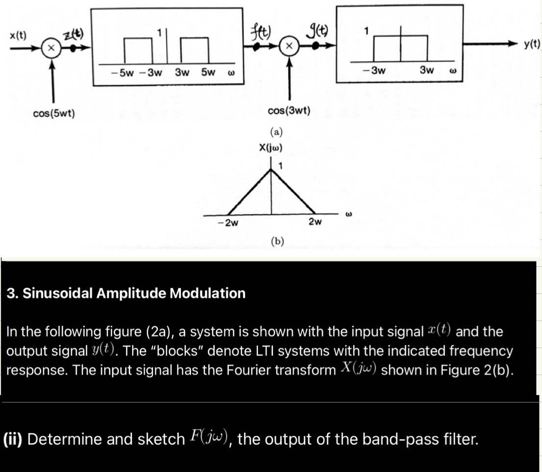
Sinusoidal Amplitude Modulation
In the following figure a a system is shown with the input signal and the output signal The "blocks" denote LTI systems with the indicated frequency response. The input signal has the Fourier transform shown in Figure b
ii Determine and sketch the output of the bandpass filter.
Step by Step Solution
There are 3 Steps involved in it
1 Expert Approved Answer
Step: 1 Unlock

Question Has Been Solved by an Expert!
Get step-by-step solutions from verified subject matter experts
Step: 2 Unlock
Step: 3 Unlock