

Question: The equivalent fan-duct network of an air condition system serving a function room is shown in Figure Q6. R1, R2 and R3 represent the
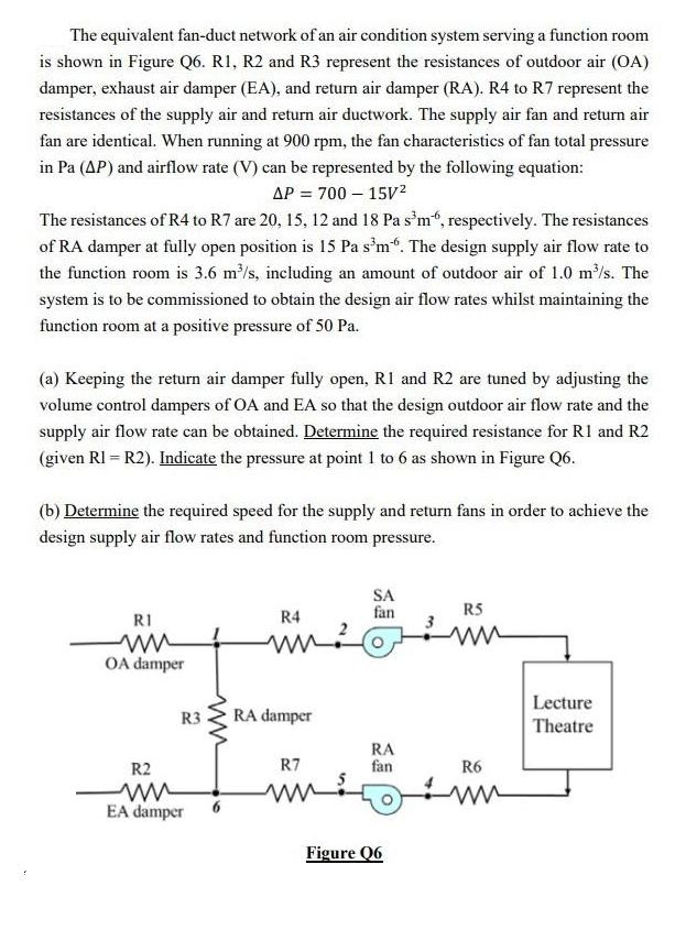
The equivalent fan-duct network of an air condition system serving a function room is shown in Figure Q6. R1, R2 and R3 represent the resistances of outdoor air (OA) damper, exhaust air damper (EA), and return air damper (RA). R4 to R7 represent the resistances of the supply air and return air ductwork. The supply air fan and return air fan are identical. When running at 900 rpm, the fan characteristics of fan total pressure in Pa (AP) and airflow rate (V) can be represented by the following equation: AP = 700 - 15V The resistances of R4 to R7 are 20, 15, 12 and 18 Pa s'm, respectively. The resistances of RA damper at fully open position is 15 Pa sm. The design supply air flow rate to the function room is 3.6 m/s, including an amount of outdoor air of 1.0 m/s. The system is to be commissioned to obtain the design air flow rates whilst maintaining the function room at a positive pressure of 50 Pa. (a) Keeping the return air damper fully open, R1 and R2 are tuned by adjusting the volume control dampers of OA and EA so that the design outdoor air flow rate and the supply air flow rate can be obtained. Determine the required resistance for R1 and R2 (given R1 = R2). Indicate the pressure at point 1 to 6 as shown in Figure Q6. (b) Determine the required speed for the supply and return fans in order to achieve the design supply air flow rates and function room pressure. RI OA damper R3 R2 ww EA damper R4 ww? RA damper R7 SA fan RA fan Figure 06 R5 m R6 Lecture Theatre The equivalent fan-duct network of an air condition system serving a function room is shown in Figure Q6. R1, R2 and R3 represent the resistances of outdoor air (OA) damper, exhaust air damper (EA), and return air damper (RA). R4 to R7 represent the resistances of the supply air and return air ductwork. The supply air fan and return air fan are identical. When running at 900 rpm, the fan characteristics of fan total pressure in Pa (AP) and airflow rate (V) can be represented by the following equation: AP = 700 - 15V The resistances of R4 to R7 are 20, 15, 12 and 18 Pa s'm, respectively. The resistances of RA damper at fully open position is 15 Pa s'm6. The design supply air flow rate to the function room is 3.6 m/s, including an amount of outdoor air of 1.0 m/s. The system is to be commissioned to obtain the design air flow rates whilst maintaining the function room at a positive pressure of 50 Pa. (a) Keeping the return air damper fully open, R1 and R2 are tuned by adjusting the volume control dampers of OA and EA so that the design outdoor air flow rate and the supply air flow rate can be obtained. Determine the required resistance for R1 and R2 (given R1 = R2). Indicate the pressure at point 1 to 6 as shown in Figure Q6. (b) Determine the required speed for the supply and return fans in order to achieve the design supply air flow rates and function room pressure. RI OA damper R3 R2 ww EA damper R4 ww? RA damper R7 SA fan RA fan Figure 06 R5 m R6 Lecture Theatre
Step by Step Solution
There are 3 Steps involved in it

Get step-by-step solutions from verified subject matter experts