

Question: A boost converter shown in Figure 3 has an input voltage of V g = 2 4 V and peak value of the [ 4
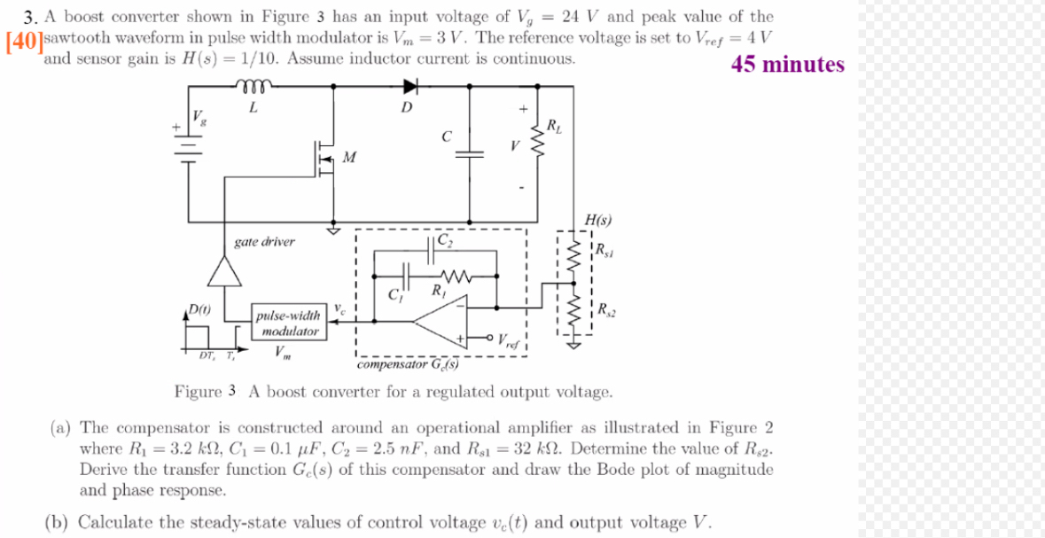
A boost converter shown in Figure has an input voltage of and peak value of the sawtooth waveform in pulse width modulator is The reference voltage is set to and sensor gain is Assume inductor current is continuous.
minutes
Figure A boost converter for a regulated output voltage.
a The compensator is constructed around an operational amplifier as illustrated in Figure where and Determine the value of Derive the transfer function of this compensator and draw the Bode plot of magnitude and phase response.
b Calculate the steadystate values of control voltage and output voltage
Step by Step Solution
There are 3 Steps involved in it
1 Expert Approved Answer
Step: 1 Unlock

Question Has Been Solved by an Expert!
Get step-by-step solutions from verified subject matter experts
Step: 2 Unlock
Step: 3 Unlock