

Question: A common actuator in control systems is the DC motor. It directly provides rotary motion and, coupled with mechanical load such as wheels or
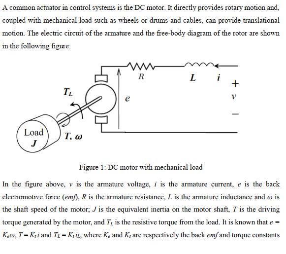
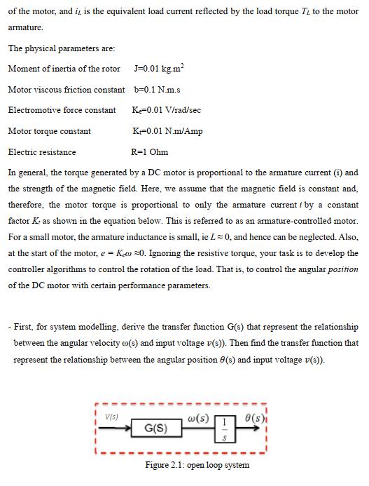
A common actuator in control systems is the DC motor. It directly provides rotary motion and, coupled with mechanical load such as wheels or drums and cables, can provide translational motion. The electric circuit of the armature and the free-body diagram of the rotor are shown in the following figure: Load J TL T. w ww R Li of the motor, and it is the equivalent load current reflected by the load torque TL to the motor armature. The physical parameters are: Moment of inertia of the rotor Motor viscous friction constant Electromotive force constant Motor torque constant Electric resistance R=1 Ohm In general, the torque generated by a DC motor is proportional to the armature current (1) and the strength of the magnetic field. Here, we assume that the magnetic field is constant and, therefore, the motor torque is proportional to only the armature current i by a constant factor K; as shown in the equation below. This is referred to as an armature-controlled motor. For a small motor, the armature inductance is small, ie L = 0, and hence can be neglected. Also, at the start of the motor, e=Ke0. Ignoring the resistive torque, your task is to develop the controller algorithms to control the rotation of the load. That is, to control the angular position of the DC motor with certain performance parameters. J=0.01 kg.m b=0.1 N.m.s Ke=0.01 V/rad/sec K-0.01 N.m/Amp - First, for system modelling, derive the transfer function G(s) that represent the relationship between the angular velocity o(s) and input voltage v(s)). Then find the transfer function that represent the relationship between the angular position (s) and input voltage v(s)). V(s) G(S) w(s) H 0(s)i Figure 2.1: open loop system
Step by Step Solution
There are 3 Steps involved in it
Answer Ans The question is based on circuit theory and laplace transformation applications Applying ... View full answer

Get step-by-step solutions from verified subject matter experts