

Question: A common-emitter (CE) bipolar junction transistor amplifier is shown in FIGURE 1. Voc i. Vs R$ CCI ww HH Ri R www W FIGURE
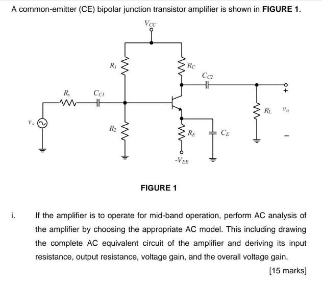
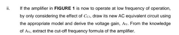
A common-emitter (CE) bipolar junction transistor amplifier is shown in FIGURE 1. Voc i. Vs R$ CCI ww HH Ri R www W FIGURE 1 Rc CC2 -VEE HH RE CE ww RL Vo If the amplifier is to operate for mid-band operation, perform AC analysis of the amplifier by choosing the appropriate AC model. This including drawing the complete AC equivalent circuit of the amplifier and deriving its input resistance, output resistance, voltage gain, and the overall voltage gain. [15 marks] ii. If the amplifier in FIGURE 1 is now to operate at low frequency of operation, by only considering the effect of Cc, draw its new AC equivalent circuit using the appropriate model and derive the voltage gain, Av. From the knowledge of Av, extract the cut-off frequency formula of the amplifier.
Step by Step Solution
There are 3 Steps involved in it
At low frequencies the coupling capacitor Ca acts like a short circuit This means that Ca can be replaced with a short circuit for lowfrequency analysis of the amplifier circuit AC Equivalent Circuit ... View full answer

Get step-by-step solutions from verified subject matter experts