

Question: A control system is shown is the next figure. The P controller will measure the current temperature vs. the desired temperature and adjust the heat
A control system is shown is the next figure. The P controller will measure the current temperature vs. the desired temperature and adjust the heat source in order to minimize the difference. The chosen mode of P controller must continuously attempt to minimize the error over time by adjusting an output variable and recalculating the error. Design the block diagram of this control system with the characteristics that are given below, and show the step by step to simulate the block diagram in Simulink.
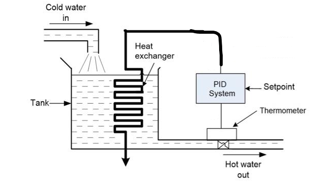
Suppose we have a water storage tank and a heat source with the following characteristics: Material: Stainless Steel Tank height (H): 10 meters Tank diameter (D): 2 meters Surface area of the tank (A): 68.4 square meters Tank volume (V): 31.4 cubic meters Discharge coefficient (Cd): 0.6 Coefficient of contraction (Cc): 0.7 Ambient temperature (Ta): 25 degrees Celsius Density of water (rho): 1000 kg/cubic meter Heat capacity of water (Cp): 4.18 kJ/(kg*degree Celsius) Input power of the heat source (Q): 500 kW Heat transfer coefficient (U): 500 W/(square meter*degree Celsius) Heat transfer area (A_heat): 5 square meters Coefficient of thermal conductivity of the tank wall (k): 0.6 W/(meter*degree Celsius) Tank wall thickness (e): 0.01 meters Distance from the liquid level to the temperature sensor (L): 1 meter Maximum tank capacity (V_max): 1000 liters Ambient temperature (T_amb): 25 degrees Celsius Initial water temperature (T_ini): 25 degrees Celsius Target temperature (T_obj): 80 degrees Celsius Tank surface area (A): 68.4 square meters In addition, we are going to use a temperature sensor (RTD), since they have a good precision and stability over time. Sensor sensitivity (K_RTD): 0.385 ohms/K Nominal resistance at 0 C: 100 Ohms Nominal resistance at 25 C: 109.73 Ohms Temperature range: -50 to 600 C. Accuracy: +/- 0.3 degrees Celsius Sensor element material: 99.99% pure platinum Sensor diameter: 4.5 mm Cable length: 1 meter Response time: 0.4 seconds (in water at 0.25 m/s).
With the parameters provided above, we can design a P-controller for the tank temperature control system in Simulink. The general steps for designing a P controller are described below: Identify the controlled variable and the manipulated variable: In this case, the controlled variable is the temperature of the water in the tank, and the manipulated variable is the input power of the heat source. Set the control target: In this case, the target is to maintain the temperature of the water in the tank at a target value of 80C. Obtain Transfer Function: It is necessary to obtain a transfer function that describes the dynamics of the system. In this case, the transfer function of the system can be obtained by applying the law of conservation of energy. The resulting equation is:
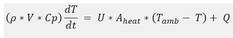
Where is the density of the water, V is the volume of the tank, Cp is the heat capacity of the water, T is the temperature of the water in the tank, U is the heat transfer coefficient, A_heat is the heat transfer area , T_amb is the ambient temperature and Q is the input power of the heat source.
The differential equation is transformed to its Laplace domain:
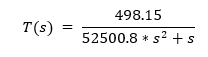
Where the numerical values of the model parameters are: Q = 500000 W = 1000 kg/m V = 31.4 m Cp = 4180 J/(kg*K) U = 500 W/(m*K) A_heat = 5 m T_room = 25C Substituting the numerical values in the equation, we have:
Determine control error: Control error is defined as the difference between the actual temperature of the water in the tank and the target temperature. For this it is necessary to establish the desired error between the target temperature and the actual temperature of the tank. In this case, we assume that the desired error is +/- 2 degrees Celsius. Therefore, the acceptable temperature range will be 78 to 82 degrees Celsius. The control error can be expressed as: error = T_obj T
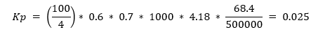
Controller Proportional Gain (Kp): The Controller Proportional Gain (Kp) must be calculated using the following formula:
Kp = (100 / acceptable_temperature_range) * Cd * Cc * rho * Cp * A / Q
Where Cd and Cc are the discharge and contraction coefficients, respectively; rho is the density of water; Cp is the heat capacity of the water; A is the surface area of the tank; Q is the input power of the heat source.
Substituting the provided values:
Proportional controller design: The controller will be of the Proportional (P) type. The controller transfer function
C(s) = Kp
Combine the transfer function of the system and the controller: The transfer function of the system is multiplied by the transfer function of the controller: G(s) = T(s) * C(s) = Kp * (Q/(VCp)s + AU)/(s + AU/(VCp))
(VCp)dtdT=UAheat(TambT)+Q T(s)=VCps+UAheat(UAheatTamb+sQ) T(s)=52500.8s2+s498.15 Kp=(4100)0.60.710004.1850000068.4=0.025
Step by Step Solution
There are 3 Steps involved in it

Get step-by-step solutions from verified subject matter experts