

Question: A structure is proposed as illustrated in Figure 3c, which is subject to a lateral vibration motion in the x-direction as indicated. This structure
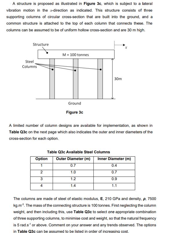
A structure is proposed as illustrated in Figure 3c, which is subject to a lateral vibration motion in the x-direction as indicated. This structure consists of three supporting columns of circular cross-section that are built into the ground, and a common structure is attached to the top of each column that connects these. The columns can be assumed to be of uniform hollow cross-section and are 30 m high. Steel Structure Columns M = 100 tonnes Ground Figure 3c 30m A limited number of column designs are available for implementation, as shown in Table Q3c on the next page which also indicates the outer and inner diameters of the cross-section for each option. Table Q3c Available Steel Columns Option Outer Diameter (m) Inner Diameter (m) 1 0.7 0.4 2 1.0 0.7 3 1.2 0.9 4 1.4 1.1 The columns are made of steel of elastic modulus, E, 210 GPa and density, p, 7500 kg.m. The mass of the connecting structure is 100 tonnes. First neglecting the column weight, and then including this, use Table Q3c to select one appropriate combination of three supporting columns, to minimise cost and weight, so that the natural frequency is 5 rad.s or above. Comment on your answer and any trends observed. The options in Table Q3c can be assumed to be listed in order of increasing cost.
Step by Step Solution
3.42 Rating (142 Votes )
There are 3 Steps involved in it
To minimize cost and weight while achieving a natural frequency of 5 rads or above we need to consid... View full answer

Get step-by-step solutions from verified subject matter experts