

Question: a) Figure Q3 shows an interfacing circuit using the 8255A in Mode 1. Port A is designed as the input port for a keyboard with
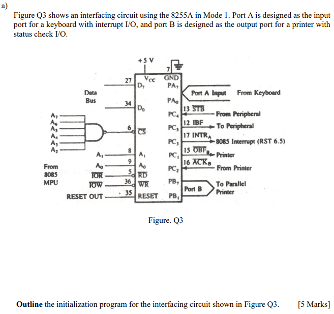
a) Figure Q3 shows an interfacing circuit using the 8255A in Mode 1. Port A is designed as the input port for a keyboard with interrupt I/O, and port B is designed as the output port for a printer with status check I/O +5 V Data Bus 6 27 Vec GND D PA, Port A Input From Keyboard 34 PA. D. 13 STB PC From Peripheral 12 IBF PCs To Peripheral 17 INTRA -8085 Interrupt (RST 6.5) 15 OBF. A PC, -Printer Mo 16 ACK PC, From Printer 36 WR PB, To Parallel 35 Port B RESET PB PC, 8 9 From 8085 MPU A, mo TOR TOW RESET OUT 5. RD Printer Figure. Q3 Outline the initialization program for the interfacing circuit shown in Figure Q3. [5 Marks)
Step by Step Solution
There are 3 Steps involved in it

Get step-by-step solutions from verified subject matter experts