

Question: (a) For the circuit given in Fig Q1(a) determine the voltage V and the current I. The diodes are ideal. 10kn skn -SV Rin
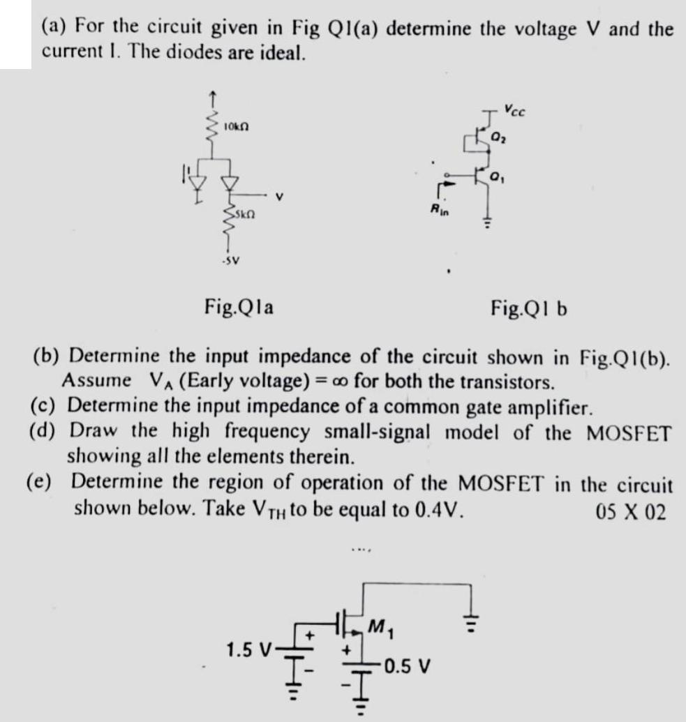
(a) For the circuit given in Fig Q1(a) determine the voltage V and the current I. The diodes are ideal. 10kn skn -SV Rin 1.5 V- M J Vcc Fig.Qla Fig.Q1 b (b) Determine the input impedance of the circuit shown in Fig.Q1(b). Assume V (Early voltage) = o for both the transistors. 0.5 V 0 (c) Determine the input impedance of a common gate amplifier. (d) Draw the high frequency small-signal model of the MOSFET showing all the elements therein. (e) Determine the region of operation of the MOSFET in the circuit shown below. Take VTH to be equal to 0.4V. 05 X 02 0
Step by Step Solution
3.46 Rating (153 Votes )
There are 3 Steps involved in it

Get step-by-step solutions from verified subject matter experts