

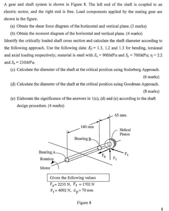
A gear and shaft system is shown in Figure 8. The left end of the shaft...
Fantastic news! We've Found the answer you've been seeking!
Question:
Expert Answer:

Related Book For 

Posted Date:
