

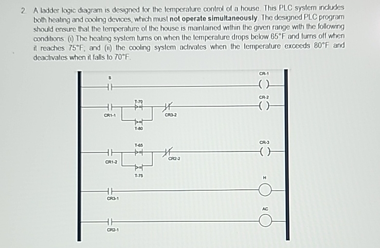
Question: A ladder logic diagram is designed for the temperature control of a house. This PLC system includes both heating and cooling devices, which must not
A ladder logic diagram is designed for the temperature control of a house. This PLC system includes both heating and cooling devices, which must not operate simultaneously. The designed PLC program should ensure that the temperature of the house is mainlained within the given range with the following conditions: i The heating system tums on when the lemperalure drops below and turns off when it reaches ; and ii the cooling system activates when the lemperature exceeds and deactivates when it falls
Step by Step Solution
There are 3 Steps involved in it
1 Expert Approved Answer
Step: 1 Unlock

Question Has Been Solved by an Expert!
Get step-by-step solutions from verified subject matter experts
Step: 2 Unlock
Step: 3 Unlock