

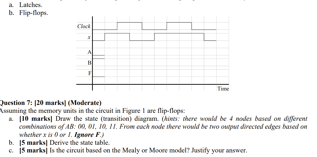
Question: a . Latches. b . Flip - flops. Question 7 : [ 2 0 marks ] ( Moderate ) Assuming the memory units in the
a Latches.
b Flipflops.
Question : marksModerate
Assuming the memory units in the circuit in Figure are flipflops:
a marks Draw the state transition diagram. hints: there would be nodes based on different combinations of AB: From each node there would be two output directed edges based on whether x is or Ignore boldsymbolF
b marks Derive the state table.
c marks Is the circuit based on the Mealy or Moore model? Justify your answer.
Step by Step Solution
There are 3 Steps involved in it
1 Expert Approved Answer
Step: 1 Unlock

Question Has Been Solved by an Expert!
Get step-by-step solutions from verified subject matter experts
Step: 2 Unlock
Step: 3 Unlock