

Question: A linear analytical model of the automobile engine for the idle speed control system is shown in Fig. 2.245.The input of the system is
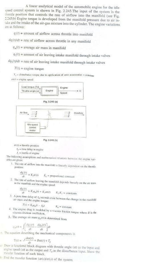
A linear analytical model of the automobile engine for the idle speed control system is shown in Fig. 2.245.The input of the system is the throule position that controls the rate of airflow into the manifold (see Fig. 2.245(b) Engine torque is developed from the manifold pressure due to air in- take and the intake of the air-gas mixture into the cylinder. The engine variations are as follows: q(t)= amount of airflow across throttle into manifold da(t)/dt = rate of airflow across throttle in any manifold 9(1) = average air mass in manifold qft)= amount of air leaving intake manifold through intake valves dy(t)/dt = rate of air leaving intake manifold through intake valves T(t) = engine torque 7, disturbance tope due to application of auto accessories = constant engine speed Load torque (Td) Throttle angle (c) Air flow Idle-speed control malar (t) throttle position Engine Fig. 2.245 (a) time delay in engine = inertia of engine de() = Ka dt Fig. 2.245 (b) Engine Speed The following assumptions and mathematical relations between the engine van ables are given: 1. The rate of airflow into the manifold is linearly dependent on the throttle position: Manifold K = proportional constant 2. The rate of airflow leaving the manifold depends linearly on the air mass in the manifold and the engine speed: dg,0) de = K + KD KK, = constants 63 dr 3. A pure time delay of 4, seconds exist between the change in the manifold air mass and the engine tonque: TU) K-5) K = constant 4. The engine drag is modeled by a viscous friction torque where B is the viscous-friction coefficient. 5. The average air mass q() is determined from 9,41) digo (1)] dt di The equation describing the mechanical components is T()=() + Boo(t) + J dt Draw a functional block diagram with throttle angle (a) as the input and engine speed (on as the output and T, as the disturbance input. Show the transfer function of each block. Find the transfer function (o(s)/er(s) of the system
Step by Step Solution
3.37 Rating (156 Votes )
There are 3 Steps involved in it
The functional block diagram for the system can be shown as follows Throttle Angle G1s Aver... View full answer

Get step-by-step solutions from verified subject matter experts