

Question: A ) Overall Structure Free Body Diagram Given the structural arm loaded perpendicular to its plane as shown below. Explore the section loads / stresses
A Overall Structure Free Body Diagram
Given the structural arm loaded perpendicular to its plane as shown below. Explore the section
loadsstresses as instructed using the coordinate systems given. The structure cross section is a
solid round. What is shown is the centerline of the bent bar.
Draw an overall FBD for the structure that has been removed from the fixed boundary condition on the left.
Try and show all force arrows in the arrows in the proper direction. Recall in statics we let the math tell us if the arrows are
wrong by a resulting negative sign. We take it to the proper level in design and industry reports where arrows are to be shown
in the correct direction which means fixing equilibrium equations and FBDs Judiciously use double arrow head convention for
moments torque or torsional loads
Overall Structure FBD
D AA Section Load Equilibrium Equations
Recall the FBD created in step which isolated or cut the structure at
Redraw the AA cut FBD with the following new variables for the complete set of reactions that could be present:
in order axial, shear, moments and torsion labeled as
Why do you think an engineer would use these particular labels for the loads or stress resultants?
On the following page write all six equilibrium equations for this FBD showing both zero and nonzero loads at section
AA
You need not solve these equations just set them up Identify which of these section loads are zero. Make sure your
arrows are in the correct directions and use the other geometry variables as given in the original sketch.
D contd. Equilibrium equations for structure cut at AA
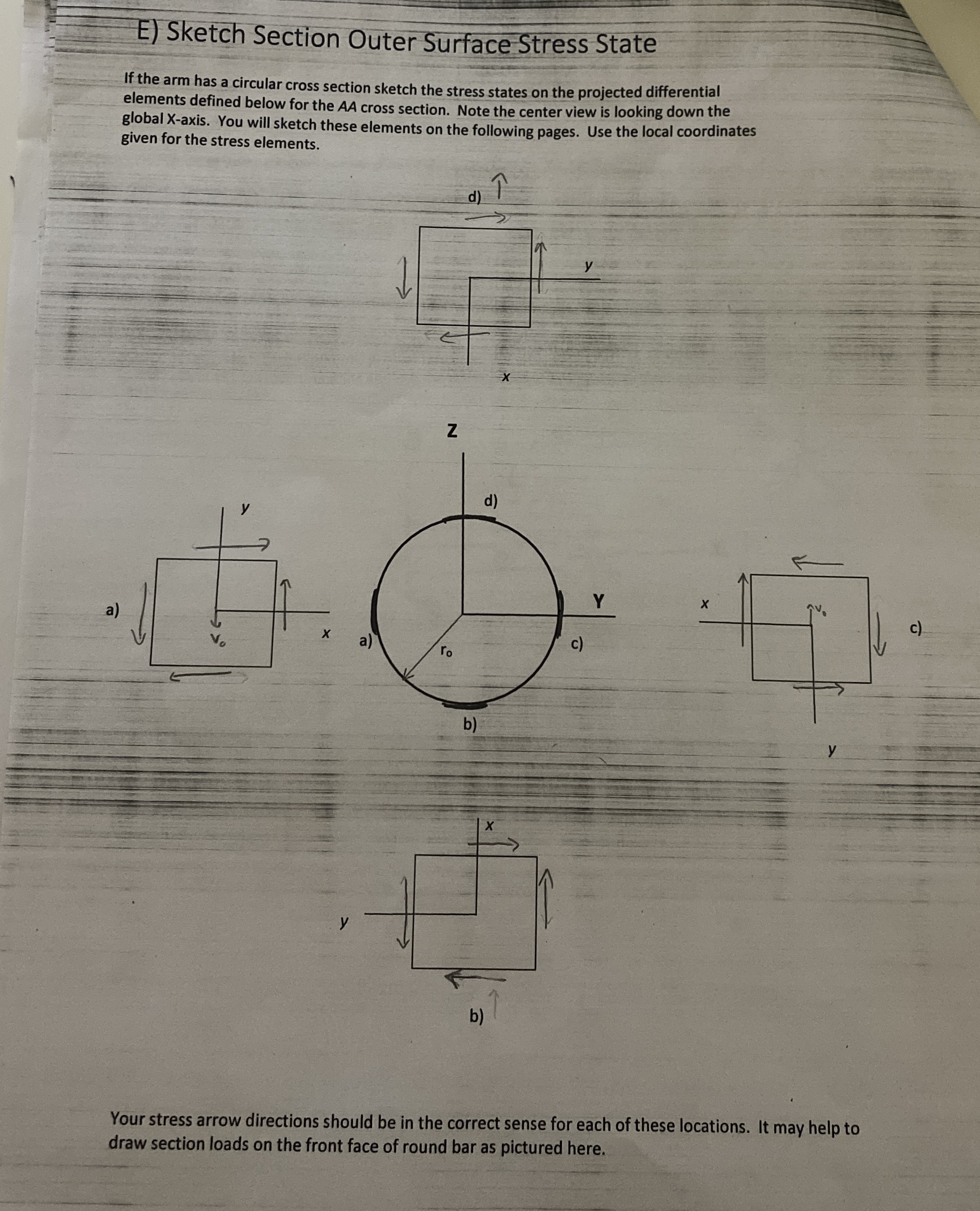
E Sketch Section Outer Surface Stress State
If the arm has a circular cross section sketch the stress states on the projected differential
elements defined below for the AA cross section. Note the center view is looking down the
global Xaxis. You will sketch these elements on the following pages. Use the local coordinates
given for the stress elements.
Step by Step Solution
There are 3 Steps involved in it
1 Expert Approved Answer
Step: 1 Unlock

Question Has Been Solved by an Expert!
Get step-by-step solutions from verified subject matter experts
Step: 2 Unlock
Step: 3 Unlock