Question: PLEASE READ CAREFULLY THE CASE STUDY PROVIDED AND FEEL FREE TO ADD HERE YOUR COMMENTS FOR EXAMPLE LIKES DISLIKES WORDS OR PHRASES YOU DO NOT
PLEASE READ CAREFULLY THE CASE STUDY PROVIDED AND FEEL FREE TO ADD HERE YOUR COMMENTS FOR EXAMPLE
LIKES
DISLIKES
WORDS OR PHRASES YOU DO NOT UNDERSTAND
ANY COMMENTS THAT WILL IMPROVE THE DIALOGUE
PLEASE DO NOT HANDWRITE
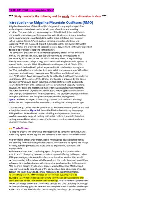
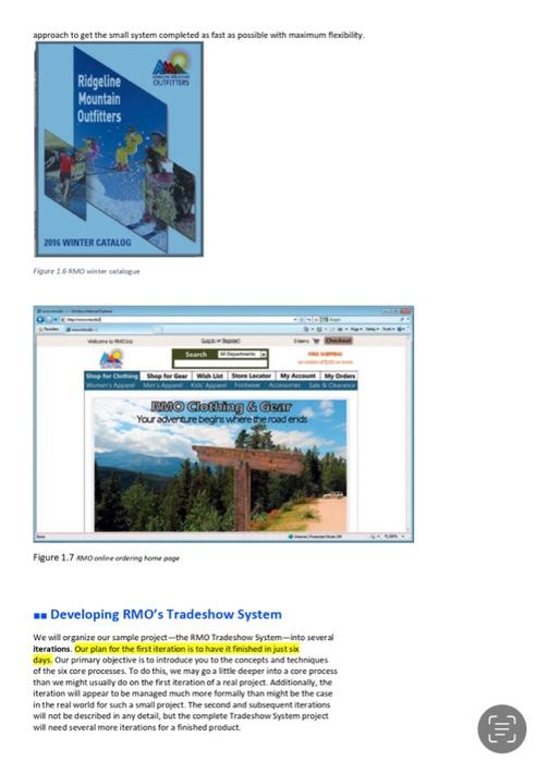
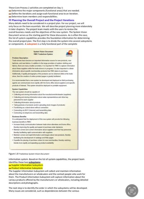
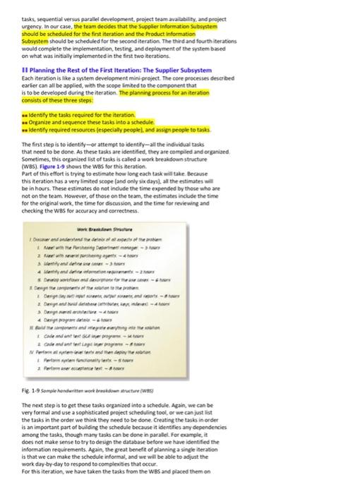
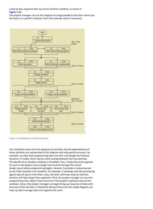
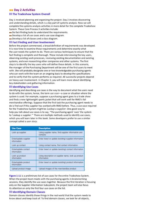
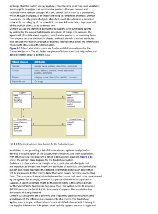
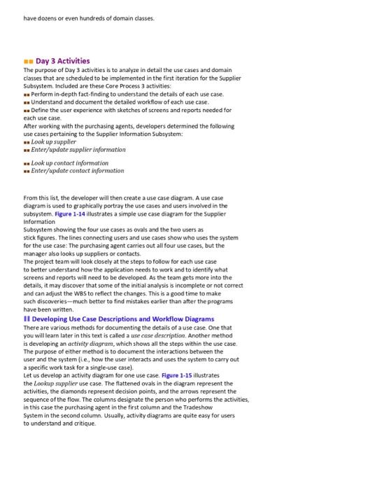
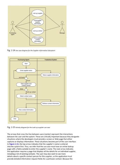
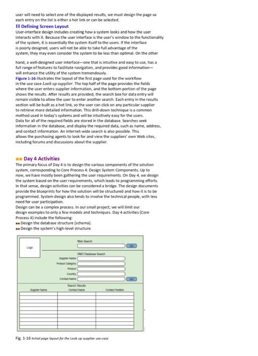
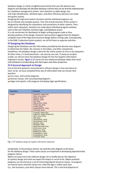
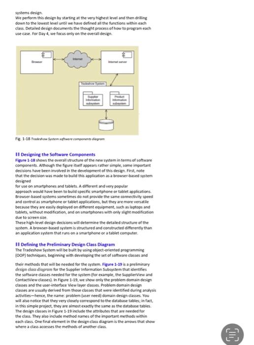
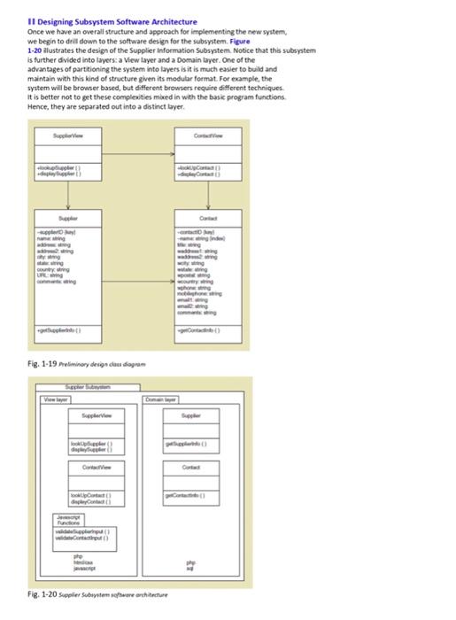
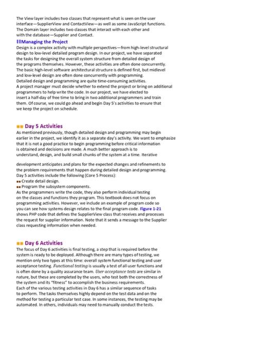
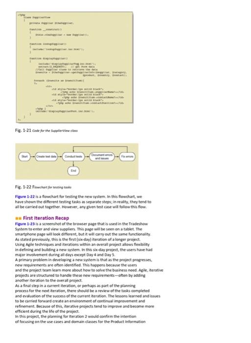
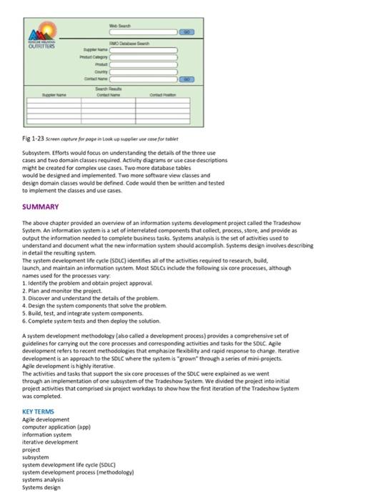
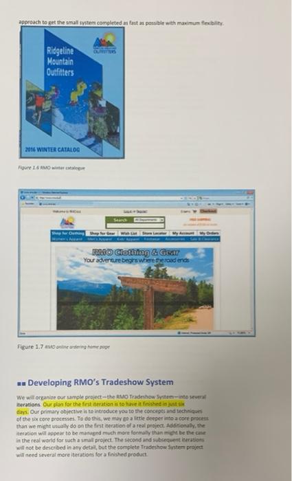
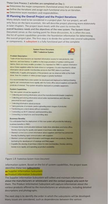
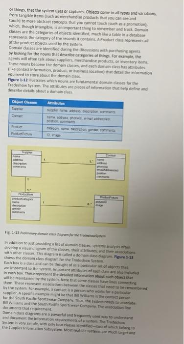
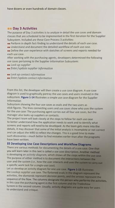
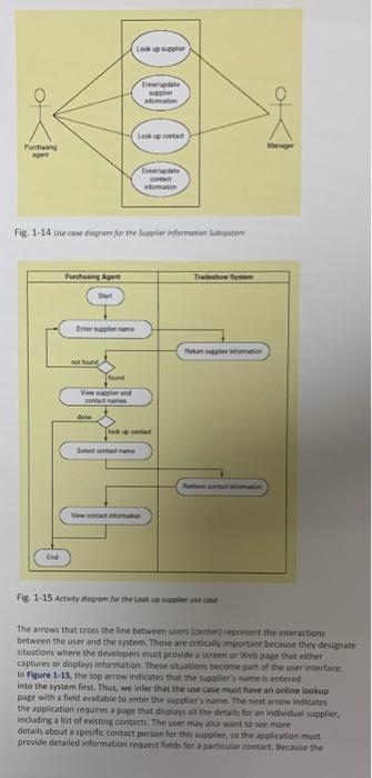
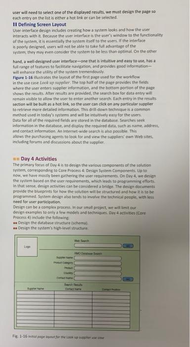
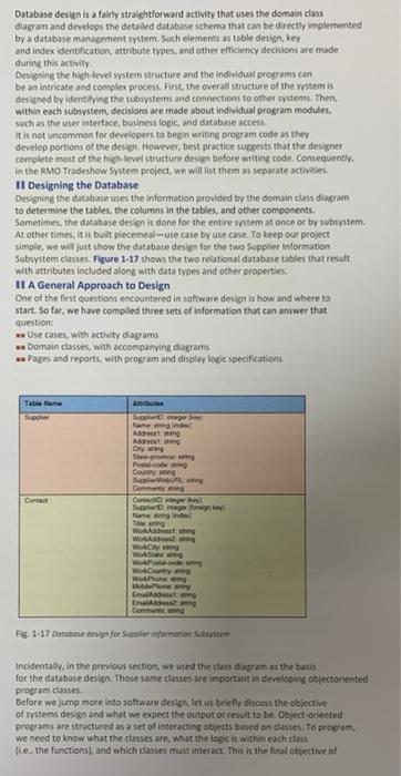
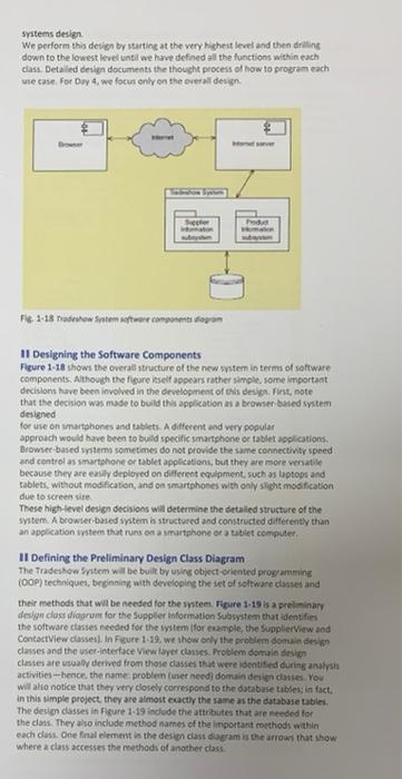
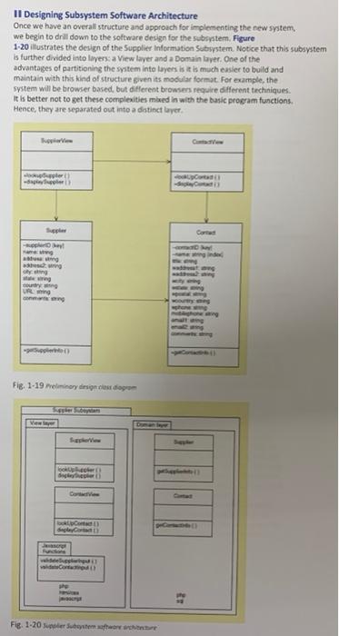
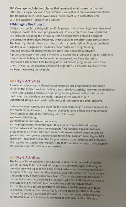
CASE STUDY#11 a complete SDL *** Study carefully the following and be ready for a discussion in class *** Introduction to Ridgeline Mountain Outfitters (RMO) Ridgeline Mountain Outfitters (RMO) is a large retail company that specializes In clothing and related accessories for all types of outdoor and sporting activities. The mountain and western regions of the United States and Canada witnessed tremendous growth in recreation activities in recent years, indoting skiing, snowboarding, mountain biking water skiing, jet skiing, niver running sailing jogging hiking ATVing cycling camping mountain climbing and rappeling. With the increased interest in outdoor sports, the market for winter and summer sports clothing and accessones exploded, so RMO continually expanded its line of sportswear to respond to this market. The company's growth charted an interesting history of mail-order, brick and mortar, and online sales. RMO got its start by selling to dothing stores in the Park City, Utah, area. In the late 1980s and early 1990s, it began selling directly to customers using catalog with maitinand telephone-order options. It opened its first store in 1994. After the Winter Olympics in Park City in 2002, business exploded and RMO quickly expanded to 10 retail outlets throughout the West and added Internet sales. Last year, retail store revenue was 557 milion Telephone and mail-order revenues were $10 million, and Internet sales were $200 million. Most sales continue to be in the West, although the market in several areas of the eastern United States and Canada is growing By the Winter Olympics in Vancouver, British Columbia, in 2008, RMO's growth and profits resulted mainly from online sales and service, as with most specialty retailers: however, the brick-and-mortar and mailorder business remained important too. After the Winter Olympics in Sochi in 2014, RMO negotiated with several Utah Olympic Medal Winners for endorsements. This provided additional interest throughout the West and instigated another period of rapid growth Figure 1-6 shows a sample of the catalog that RMO still mails out. Although mail-order and telephone sales are modest, receiving the catalog encourages customers to go online to make purchases, so RMO continues to produce and mail abbreviated versions. Figure 1-7 shows the AMO online ordering home page RMO produces its own line of outdoor clothing and sportswear. However, to offer a complete range of clothing in its retail outlets, it also sell brands of clothing sourced from other vendors. Furthermore, most accessories sold are sourced through vendors. Trade Shows To keep its product line innovative and responsive to consumer demand, RO'S purchasing agents attend apparel and accessory trade shows around the world where vendors exhibit their merchandine. RMO is good at anticipating trends and profiting from interesting vendor specials. Furthermore, its agents are always watching for new products and accessories to expand RMO's product line appropriately At the trade shows,RMO purchasing agents frequently find products they want to add to the spring summer, or winter apparel offering. In the past, when RMO purchasing agents wanted to place an order with a vendor, they would exchange contact information with the vendor at the trade show and would then follow up via e- mails and phone calls to create a purchase order. In the current 24/7 business dimate, this business process was just too slow. RMO needed to speed things up to keep ahead of the competition, take advantage of vendor deals at the trade shows and be more responsive to customer demands To solve this problem, RM initiated an information system project to develop a system for collecting and tracking Information about suppliers and about products added to its merchandise offerings. The Tradeshow System needs to take advantage of the latest in wireless devices and data capturing technology to allow purchasing agents to research and complete purchase orders on the spot at the trade shows. AMO decided to use an agile, iterative project management approach to get the small system completed as fast as possible with maximum flexibility OUTFITS Ridgeline Mountain Outfitters 2016 WINTER CATALOG Figure 16 AMO wiele w Search Shop for using Shop for Gear With Store Lacey Art WO Clothing & Gear Your adventure begrs where the roadence Figure 1.7 MMO online ordering home page - Developing RMO's Tradeshow System We will organize our sample project--the RMO Tradeshow System-into several iterations. Our plan for the first iteration is to have it finished in just six days. Our primary objective is to introduce you to the concepts and techniques of the score processes. To do this, we may go a little deeper into a core process than we might usually do on the first iteration of a real project. Additionally, the iteration will appear to be managed much more formally than might be the case in the real world for such a small project. The second and subsequent iterations will not be described in any detail, but the complete Tradeshow System project will need several more iterations for a finished product. Il Most new information system applications require a project with several iterations. In the first iteration, there are usually three major objectives. The first objective is to get project approval. The second objective is to get a dear picture of the system's overall vision-the overall functions and data requirements. The third objective is to determine the detailed specifications and develop a solution for one portion of the system (ie, actually analyze, design, build, and test one part of the system. The second and third iterations would continue to work on the additional portions of the system based on the system vision In our project, we will touch on all these objectives within the first iteration We will show an example of a System Vision Document and then develop one portion of the overall system. It should be noted that the division of this project into days and daily activities are somewhat arbitrary. The following organization is quite workable, but it is not the only way to organize the project. - Initial Project Activities Before the project actually begins, the head of RMO's Purchasing Department works with a systems analyst to identify and document the specific business need and to define the project objectives. RMO's management then reviews the primary project objectives and provides budget approval. Every organization has to give budget approval before a project can start. Some organizations have a formal process to get a project approved, other organizations have a less-formal process. Although these activities are part of Core Process of the SDLC, they are often completed well in advance of the start of the first project iteration, They might be called pre-project activities of Core Process 1: - Identify the problem and document the objective of the solution system - Obtain approval to commence the project. Il System Vision Document As with all new projects within RMO, a System Vision Document is developed to identity the benefits to the company and the functional capabilities that will be included in the system. Frequently, this is done in two steps developing a preliminary statement of benefits and then adding estimates of specific dollar costs and dollar benefits. Figure 1-8 is the System Vision Document for this project As described earlier, RMO needs a mobile system that can be used by its purchasing agents as they attend various product, dothing, and fabric trade shows. The system needs to fulfill two major requirements. First, it has to have the functionality to capture information about suppliers and products. Second, it needs to be able to communicate with the home office systems, and because these trade shows are held in various venues around the world, various methods of connectivity are needed. The preliminary investigation included various equipment options, like notebook computers, tablets, and smartphones Smartphones appeared to have the best connection options, but their small size made viewing the details of photographs somewhat difficult, the iPad and other portable tablets with advanced connectivity options also appear to be viable options. Because smartphones and tablets have similar requirements, analysts determine to develop an application that will execute on either type of device, giving purchasing agents multiple options for system access Toward the end of the initial project activities, a meeting is held involving all the key persons, including a representative of executive management. The decision is made to move ahead with the project and budget the necessary funds. Day 1 Activities II RMO-Tradeshow System Overall The project actually begins with Day 1, which is essentially a planning day Usually, the project team first reviews the System Vision Document and verifies that the preliminary work is still valid. It reviews the scope of the project to become familiar with the problem, and then it plans the iterations and activities for the remainder of the project. The second SDLC core process-Plan and monitor the project-includes business analysis and project management activities These Core Process 2 activities are completed on Day 1 - Determine the major components (functional areas) that are needed. -- Define the iterations and assigneach functional area to an iteration - Determine team members and responsibilities Il Planning the Overall Project and the Project Iterations Many details need to be considered in a project plan. For our project, we will only focus on the bare essentials. We will describe project planning more elaborately in later chapters. The project team meets with the users to review the overall business needs and the objectives of the new system. The System Vision Document serves as the starting point for these discussions. As is often the case. the list of system capabilities provides the foundation information for determining the overall project plan. The first step is to divide the system into several subsystems or components. A subsystem is a fully functional part of the complete Von Document To po want to the largest Wom www woord Algemene common with home System Cap The new De gode Collecting and personal or Categorie Tandem Funghi Coro Berte terit tanto the topic urance and to end tyring och Mancomenda y pay papa oder die deyd edib Figure 1.8 Tradeshow System Vion Document information system. Based on the list of system capabilities, the project team identifies these two subsystems Supplier information Subsystem Product Information Subsystem The Supplier information Subsystem will collect and maintain information about the manufacturers or wholesalers and the contact people who work for them. The Product Information Subsystem will capture information about the various products offered by the manufacturers or wholesalers, including detailed descriptions and photographs The next step is to identify the order in which the subsystems will be developed Many issues are considered, such as dependencies between the various (10) tasks, sequential versus parallel development project team availability, and project urgency. In our case, the team decides that the Supplier information Subsystem should be scheduled for the first iteration and the Product Information Subsystem should be scheduled for the second iteration. The third and fourth iterations would complete the implementation testing and deployment of the system based on what was initially implemented in the first two iterations 11 Planning the rest of the First Iteration: The Supplier Subsystem Each iteration is like a system development miniproject. The core processes described earlier can all be applied, with the scope limited to the component that is to be developed during the iteration. The planning process for an iteration consists of these three steps: - identify the tasks required for the iteration - Organize and sequence these tasks into a schedule. - Identity required resources (especially people, and assig people to tasks. The first step is to identify or attempt to identity-all the individual tasks that need to be done. As these tasks are identified, they are compiled and organized Sometimes, this organized list of tasks is called a work breakdown structure (WBS). Figure 1-9 shows the was for this iteration Part of this effort is trying to estimate how long each task will take Because this iteration has a very limited scope and only six days. all the estimates will be in hours. These estimates do not include the time expended by those who are not on the team. However, of those on the team, the estimates include the time for the original work, the time for discussion, and the time for reviewing and checking the WBS for accuracy and correctness Porn - 2 where yen deine- - Doe- be Deng- die Det er be www Center Gde dan tanpa Weleda Fotos Reserler - Fig 1-9 Somplete workers The next step is to get these tasks organised into a schedule. Again, we can be very formal and use a sophisticated project scheduling tool, or we can just list the tasks in the order we think they need to be done. Creating the tasks in order is an important part of building the schedule because it identifies any dependencies among the tasks, though many tasks can be done in parallel. For example, it does not make sense to try to design the database before we have identified the information requirements. Again, the great benefit of planning a single iteration is that we can make the schedule informal, and we will be able to adjust the work day-by-day to respond to complexities that occur. For this iteration, we have taken the tasks from the WBS and placed them on a day by day sequence that we call an iteration schedule, as shown in Figure 1-10 The project manager can use this diagram to assign people to the tasks and to put the tasks on a specific schedule chart with calendar dates if necessary H Putinom ch 11 Dodom 1 ch Gde For 1.20 Schedule for the first teration You should be aware that the sequence of activities and the dependencies of those activities are represented in this diagram with only partial accuracy. For example, we show that programming does not start until design has finished However, in reality, there may be some overlap between the two activities. The benefit of an iteration schedule is threefold. Fiest, it helps the team organise its work so developers have enough time to think through the critical design issues before programming begins. Second, it provides a measuring rod to see if the iteration is on schedule. For comple, meeting with the purchasing agents take all day or more than a a day, the team will know early on that this iteration will take longer than expected. Third, the project manager can see that programming may require more resources if the project is going to stay on this schedule. Hence, the project manager can begin lining up resources to help with that part of the iteration. It should be obvious that even this simple diagram can help a project manager plan and organize the work Day 2 Activities Il The Tradeshow System Overall Day 1 involved planning and organizing the project Day 2 involves discovering and understanding details, which is a key part of systems analysis. Now we wil complete the systems analysis activities in more detail for the complete Tradeshow System. These Core Process 3 activities include: Do fact-finding tasks to understand the requirements. - Develop a list of use cases and a use case diagram - Develop a list of classes and a class diagram. H Fact Finding and User Involvement Before the project commenced, a broad definition of requirements was developed It is now time to examine those requirements and determine exactly what the user needs the system to do. There are various techniques to ensure that the fact finding is complete and thorough. These include interviewing the key users, observing existing work processes, reviewing existing documentation and existing systems, and even researching other companies and other systems. The first step is to identify the key users who will define these details. In this scenario, the manager of the Purchasing Department will be one of the first users to meet with. She will probably designate one or two knowledgeable purchasing agents who can work with the team on an ongoing basis to develop the specifications and to verify that the system performs as required. All successful projects depend on heavy user involvement. In Chapter 2. you will learn more about identifying key stakeholders and gathering information H identifying Use Cases identifying and describing use cases is the way to document what the users need to do with the system, hence, the term use case-a case or situation where the system is used. For example, suppose a purchasing agent goes to a trade show and finds a new lightweight sports jacket that will work well for RMO's fall merchandise offerings. Suppose that the first task the purchasing agent needs to dois find out if this supplier has worked with RMO before. Thus, a use case required for the Tradeshow System might be Lookup a supplier. One good way to help you talk about use cases is to say, "The purchasing agent uses the system to lookup a supplier. There are multiple methods used to identify use cases, which you will learn later in this book. Some developers prefer to use a similar concept called a user story Use Case Description Look up supplier Uning suppler name find supplier information and contacts Entendatur Enter now or update in conformation information Lock contact Using contact me find contact information Endate conta Coworoduto contact information formation Look up product Uning ortion of pokup product information Entotdate product Entert or update og product information information Upload product image Ubroad images of the mechandos product Figure 1-11 is a preliminary list of use cases for the entire Tradeshow System. When the project team meets with the purchasing agents in brainstorming sessions, they identify the use cases together. Because the first iteration is focusing only on the supplier information Subsystem, the project team will also focus its attention on only the first four use cases on the list. Il Identifying Domain Classes Domain classes identify those things in the real world that the system needs to know about and keep track of. To find domain classes, we look for all objects, or things, that the system uses or captures. Objects come in all types and variations, from tangible items (such as merchandise products that you can see and touch) to more abstract concepts that you cannot touch (such as a promotion). which, though intangible, is an important thing to remember and track. Domain classes are the categories of objects identified, much like a table in a database represents the category of the records it contains. A Product class represents all of the product objects used by the system. Domain classes are identified during the discussions with purchasing agents by looking for the nouns that describe categories of things. For example, the agents wil often talk about suppliers, merchandise products, or inventory items These nouns become the domain classes, and each domain class has attributes like contact information, product, or business location) that detail the information you need to store about the domain class Figure 1-12 illustrates which nouns are fundamental domain classes for the Tradeshow System. The attributes are pieces of information that help define and describe details about a domain class. Object Class Supplier Attributes plename crtion commands med honest pobo com category.namento gender.com Ome Product Productcture Pro Fig. 1-13 Preliminary domain clau diogram for the Tradeshow System In addition to just providing a list of domain classes, systems analysts often develop a visual diagram of the classes, their attributes, and their associations with other classes. This diagram is called a domain class diagram. Figure 1-13 shows the domain class diagram for the Tradeshow System Each box is a class and can be thought of as a particular set of objects that are important to the system. Important attributes of each dass are also included in each box. These represent the detailed information about each object that will be maintained by the system. Note that some classes have lines connecting them. These represent associations between the classes that need to be remembered by the system. For example, a contact is a person who works for a particular supplier. A specific example might be that in Wiliams is the contact person for the South Pacific Sportswear Company, Thus, the system needs to associate Bal Williams and the South Pacific Sportswear Company. The association line documents that requirement Domain class diagrams are a powerful and frequently used way to understand and document the information requirements of a system. The Tradeshow System is very simple, with only four dasses identified-two of which belong to the Supplier information Subsystem. Most real-life systems are much larger and have dozens or even hundreds of domain classes. w Day 3 Activities The purpose of Day 3 activities is to analyze in detail the use cases and domain classes that are scheduled to be implemented in the first iteration for the Supplier Subsystem. Included are these Core Process 3 activities: - Perform in-depth fact-finding to understand the details of each use case. Understand and document the detailed workflow of each use case. -- Define the user experience with sketches of screens and reports needed for each use case After working with the purchasing agents, developers determined the following use cases pertaining to the supplier information Subsystem: - Look up supplier --Enter/update supplier information Look up contact information -- Enter/update contact information From this list, the developer will then create a use case diagram. A use case diagram is used to graphically portray the use cases and users involved in the subsystem. Figure 1-14 illustrates a simple use case diagram for the Supplier Information Subsystem showing the four use cases as ovals and the two users as stick figures. The lines connecting users and use cases show who uses the system for the use case: The purchasing agent carries out all four use cases, but the manager also looks up suppliers or contacts The project team will look closely at the steps to follow for each use case to better understand how the application needs to work and to identify what screens and reports will need to be developed. As the team gets more into the details, it may discover that some of the initial analysis is incomplete or not correct and can adjust the WBS to reflect the changes. This is a good time to make such discoveries-much better to find mistakes earlier than after the programs have been written Il Developing Use Case Descriptions and Workflow Diagrams There are various methods for documenting the details of a use case. One that you will learn later in this text is called a use case description. Another method is developing an activity diagram, which shows all the steps within the use case. The purpose of either method is to document the interactions between the user and the system (ie, how the user interacts and uses the system to carry out a specific work task for a single-use case) Let us develop an activity diagram for one use case. Figure 1-15 illustrates the Lookup supplier use case. The flattened ovals in the diagram represent the activities, the diamonds represent decision points, and the arrows represent the sequence of the flow. The columns designate the person who performs the activities, in this case the purchasing agent in the first column and the Tradeshow System in the second column. Usually, activity diagrams are quite easy for users to understand and critique Lock Ele Fig. 1-14 die case diagram for the supplier information Substem Thing Agent Trade Vid G 11:01 End Fig. 1-15 Atbity diagram for the Look up supplier se me The arrows that cross the line between users (center) represent the interactions between the user and the system. These are critically important because they designate situations where the developers must provide a screen or Web page that either captures or displays information. These situations become part of the user interface In Figure 1-15, the top arrow indicates that the supplier's name is entered into the system first. Thus, we inter that the use case must have an online Lookup page with a field available to enter the supplier's name. The next arrow indicates the application requires a page that displays all the details for an individual supplier including a list of existing contacts. The user may also want to see more details about a specific contact person for this supplies, so the application must provide detailed information request fields for a particular contact. Because the user will need to select one of the displayed results, we must design the page so each entry on the list is either a hot link or can be selected Il Defining Screen Layout User-interface design indudes creating how a system looks and how the user interacts with it. Because the user interface is the user's window to the functionality of the system, is essentially the system itself to the users. If the interface is poorly designed, users will not be able to take full advantage of the system, they may even consider the system to be less than optimal. On the other hand, a well-designed user interface-one that is intuitive and easy to use, has a full range of features to facilitate navigation and provides good information- will enhance the utility of the system tremendously Figure 1-16 illustrates the layout of the first page used for the workflow in the use case Look up supplier. The top half of the page provides the fields where the user enters supplier information, and the bottom portion of the page shows the results. After results are provided the search box for data entry will remain visible to allow the user to enter another search. Each entry in the results section will be built as a hot link, so the user can click on any particular supplier to retrieve more detailed information. This drill-down technique is a common method used in today's systems and will be intuitively easy for the users Data for all of the required fields are stored in the database. Searches seek information in the database, and display the required data, such as name, address, and contact information. An Internet-wide search is also possible. This allows the purchasing agents to look for and view the suppliers' own web sites including forums and discussions about the supplier w Day 4 Activities The primary focus of Day 4 is to design the various components of the solution system, corresponding to Core Process 4, Design System Components. Up to now, we have mostly been gathering the user requirements. On Day 4 we design the system based on the user requirements, which leads to programming efforts. In that sense, design activities can be considered a bridge. The design documents provide the blueprints for how the solution will be structured and how it is to be programmed System design also tends to involve the technical people with less need for user participation Design can be a complex process. In our small project, we will limit our design examples to only a few models and techniques Day 4 activities (Core Process 4) include the following Design the database structure (schema) - Design the system's high-level structure Guy Fig 1-16 Initial page layout for the look up preces Database design is a fairly straightforward activity that uses the domain class diagram and develop the detailed database schema that can be directly implemented by a database management system. Such elements as table design, key and index identification, attribute types, and other efficiency decisions are made during this activity Designing the high-level system structure and the individual programs can be an intricate and complex process. First, the overall structure of the systems designed by identifying the subsystems and connections to other systems. Then, within each subsystem, decisions are made about individual program modules such as the user interface, business logic, and database access it is not uncommon for developers to begin writing program code as they develop portions of the design. However, best practice suggests that the designer complete most of the high-level structure design before writing code. Consequently in the RMO Tradeshow System project, we will list them as separate activities Il Designing the Database Designing the database uses the information provided by the domain class diagram to determine the tables, the columns in the tables, and other components. Sometimes, the database design is done for the entire system at once or by subsystem At other times, it is built piecemeal-use case by use case. To keep our project simple, we will just show the database design for the two Supplier information Subsystem classes. Figure 1-17 shows the two relational database tables that result with attributes included along with data types and other properties II A General Approach to Design One of the first questions encountered in software design is how and where to start so far, we have compiled three sets of Information that can answer that question - Use cases, with activity diagrams Domain classes, with accompanying diagrams - Pages and reports, with program and display logic specifications ge Adet Ah Oy Se County Dan Cartel Bowl TI W W wear WC Wh More E Ema Fig. 1-17 Database design for Supplier information System Incidentally, in the previous section, we used the dass diagram as the basis for the database design Those same classes are important in developing objectoriented program dasses Before we jump more into software design, let us briefly discuss the objective of systems design and what we expect the output or result to be Object-oriented programs are structured as a set of interacting objects based on classes. To program we need to know what the classes are, what the logic is within each class lie, the functions), and which dasses must interact. This is the final objective of systems design We perform this design by starting at the very highest level and then drilling down to the lowest level until we have defined all the functions within each class. Detailed design documents the thought process of how to program each use case. For Day 4 we focus only on the overall design Fle 1-18 Tradeshow Saten frere components open Il Designing the Software Components Figure 1-18 shows the overall structure of the new system in terms of software components. Although the figure itself appears rather simple, some important decisions have been involved in the development of this design. First, note that the decision was made to build this application as a browser based system designed for use on smartphones and tablets. A different and very popular approach would have been to build specific smartphone or tablet applications Browser-based systems sometimes do not provide the same connectivity speed and control as smartphone or tablet applications, but they are more versatile because they are easily deployed on different equipment, such as laptops and tablets, without modification, and on smartphones with only slight modification due to screen size These high-level design decisions will determine the detailed structure of the system. A browser-based system is structured and constructed differently than an application system that runs on a smartphone or a tablet computer II Defining the Preliminary Design Class Diagram The Tradeshow System will be built by using object-oriented programming (OOP) techniques, beginning with developing the set of software classes and their methods that will be needed for the system. Figure 1-19 is a preliminary desigo dass diagram for the Supplier information Subsystem that identifies the software classes needed for the system for comple, the Supplierview and ContactView classes). In Figure 1-19, we show only the problem domain design classes and the user interface View layer dasses Problem domain design classes are usually derived from those classes that were identified during analysis activities-hence, the name problem (user need domain design dasses. You will also notice that they very closely correspond to the database tables, in fact, In this simple project, they are almost exactly the same as the database tables The design classes in Figure 1-19 include the attributes that are needed for the class. They also include method names of the important methods within each class. One final element in the design class diagram is the arrows that show where a class accesses the methods of another class 30 Il Designing Subsystem Software Architecture Once we have an overall structure and approach for implementing the new system, we begin to drill down to the software design for the subsystem. Figure 1-20 illustrates the design of the Supplier information Subsystem. Notice that this subsystem is further divided into layers: a View layer and a Domain layer. One of the advantages of partitioning the system into layers isitis much easier to build and maintain with this kind of structure given its modular format. For example, the system will be browser based, but different browsers require different techniques it is better not to get these complexities mied in with the basic program functions Hence, they are separated out into a distinct byer Sii GO country wa wewe . who Fig. 1-19 Preliminary design del forum Geplante Input Fig. 1-20 Supplier Subaystemswore architecture The View layer includes two classes that represent what is seen on the user interface-Supplierview and ContactView-as well as some JavaScript functions The Domain layer includes two dasses that interact with each other and with the database --Supplier and Contact II Managing the Project Design a complex activity with multiple perspectives from high-level structural design to low-level detailed program design in our project, we have separated the tasks for designing the overall system structure from detailed design of the programs themselves. However, these activities are often done concurrently The basic high-level software architectural structure is defined first, but midlevel and low-level design are often done concurrently with programming Detailed design and programming are quite time-consuming activities A project manager must decide whether to extend the project or bring an additional programmers to help write the code. In our project, we have elected to insert a half day of free time to bring in two additional programmers and train them. Of course, we could go ahead and begin Day 5's activities to ensure that we keep the project on schedule. se Day 5 Activities As mentioned previously, though detailed design and programming may begin earlier in the project, we identify it as a separate day's activity. We want to emphasize that it is not a good practice to begin programming before critical information is obtained and decisions are made. A much better approach is to understand, design, and build small chunks of the system at a time. Iterative development anticipates and plans for the expected changes and refinements to the problem requirements that happen during detailed design and programming Day 5 activities include the following (Core Process Create detail design - Program the subsystem components As the programmers write the code, they also perform individual testing on the classes and functions they program. This textbook does not focus on programming activities. However, we include an example of program code so you can see how systems design relates to the final program code. Figure 1-21 shows PHP code that defines the SupplierView class that receives and processes the request for supplier information. Note that it sends a message to the Supplier class requesting information when needed Day 6 Activities The focus of Day 6 activities is final testing a step that is required before the system is ready to be deployed. Although there are many types of testing, we mention only two types at this time overall system functional testing and user acceptance testing, Functional testing is usually a test of all user functions and is often done by a quality assurance team User acceptance tests are similar in nature, but these are completed by the users, who test both the correctness of the system and its fitness to accomplish the business requirements Each of the various testing activities in Day 6 has a similar sequence of tasks to perform. The tasks themselves highly depend on the test data and on the method for testing a particular test case. In some instances, the testing may be automated. In others, individuals may need to manually conduct the tests. Fig. 1-21 Code for the supplerView.com Do Fig. 1-22 Flowchart for testing tasks Figure 1-22 is a flowchart for testing the new system. In this flowchart, we have shown the different testing tasks as separate steps in reality, they tend to all be carried out together. However, any given test case will follow this flow First Iteration Recap Figure 1-23 is a screenshot of the browser page that is used in the Tradeshow System to enter and view suppliers. This page will be seen on a tablet. The smartphone page will look different, but it will carry out the same functionality As stated previously, this is the first six day) iteration of a longer project. Using Agile techniques and iterations within an overall project allows flexibility in defining and building a new system. In this six day project, the users have had major involvement during all days except Day and Day 5 A primary problem in developing a new system is that as the project progresses, new requirements are often identified. This happens because the users and the project team learn more about how to solve the business need. Agile, derative projects are structured to handle these new requirements-often by adding another iteration to the overall project. As a final step in a current iteration, or perhaps as part of the planning process for the next iteration, there should be a review of the tasks completed and evaluation of the success of the current iteration. The lessons learned and issues to be carried forward create an environment of continual improvement and refinement. Because of this, iterative projects tend to improve and become more efficient during the life of the project. In this project, the planning for Iteration 2 would confirm the intention of focusing on the use cases and domain classes for the Product Information AL OUTRITIS Fig 1-23 Screen capture for pope in Look up wolier se confortable Subsystem. Efforts would focus on understanding the details of the three use cases and two domain classes required. Activity diagrams or use case descriptions might be created for complex use cases. Two more database tables would be designed and implemented. Two more software view classes and design domain classes would be defined. Code would then be written and tested to implement the classes and use cases SUMMARY The above chapter provided an overview of an information systems development project called the Tradeshow System An information system is a set of interrelated components that collect, process, store, and provide as output the information needed to complete business tasks. Systems analysis is the set of activities used to understand and document what the new information system should accomplish. Systems design involves describing in detail the resulting system. The system development life cycle (SDLC) identifies all of the activities required to research, build launch, and maintain an information system. Most SOLCs include the following six core processes, although names used for the processes vary 1. Identify the problem and obtain project approval 2. Plan and monitor the project. 3. Discover and understand the details of the problem. 4. Design the system components that solve the problem 5. Build, test, and integrate system components 6. Complete system tests and then deploy the solution A system development methodology (also called a development process) provides a comprehensive set of guidelines for carrying out the core processes and corresponding activities and tasks for the SDLC Agile development refers to recent methodologies that emphasize flexibility and rapid response to change iterative development is an approach to the SOLC where the system is grown through a series of miniprojects Agile development is highly iterative The activities and tasks that support the six core processes of the SDLC were explained as we went through an implementation of one subsystem of the Tradeshow System. We divided the project into initial project activities that comprised six project workdays to show how the first iteration of the Tradeshow System was completed KEY TERMS Agile development computer application app) information system iterative development project subsystem system development life cycle (SLC) system development process methodology systems analysis Systems design CASE STUDY#11 a complete SDLC *** Study carefully the following and be ready for a discussion in class *** Introduction to Ridgeline Mountain Outfitters (RMO) Ridgeline Mountain Outfitters (RM) is a large retail company that speciales In dothing and related accessories for all types of outdoor and sporting activities. The mountain and western regions of the United States and Canada witnessed tremendous growth in recreation activities in recent years, including skin towboarding mountain bine, water stijene river running sailing, looing, hiking, Atving, cycling camping mountain climbing and rappeling with the increased interest in outdoor sports, the market for winter and summer sports clothing and accessories exploded, so RMO continually expanded its line of sportswear to respond to this market The company's growth charted an interesting history of mailorder, brick and mortar, and online sales AMO got its start by seling to clothing Stores in the Park City, Utah, area. In the late 1980s and early 1990s, it began seling directly to customers using catalogs with main and telephone order options. It opened its first store in 1994. After the Winter Olympies in Park City in 2002, business exploded and PMO quickly expanded 10 10 retail outlets throughout the West and added Internet sales. Last year, retail store revenue was 567 million telephone and mailorder revenues were $10 million, and internet sales were 5200 million. Most sales continue to be in the West, although the marketin several areas of the eastern United States and Canada is growing By the Winter Olympics in Vancouver, British Columbia, in 2008, RMO's growth and profits resulted mainly from online sales and service, as with most specialty retailers however, the brick-and-mortar and mail-order business remained important too. After the Winter Olympics in Sochi in 2014, RMO negotiated with several Utah Olympic Medal Winners for endorsements. This provided additional interest throughout the West and instigated another period of rapid growth Figure 1-6 shows a sample of the catalog that MO still mails out. Although mail-order and telephone sales are modest, receiving the catalog encourages customers to go online to make purchases, to RMO continues to produce and all abbreviated version Figure 1.7 shows the One Ordering home page RMO produces its own line of outdoor clothing and sportswear However, to offer a complete range of clothing in its retail outlets, it ses brands of clothing sourced from other vendors. Furthermore, most accessories sold are sourced through vendors w Trade Shows To keep its product line innovative and responsive to consumer demand, AMO'S purchasing agents attend apparel and accessory trade shows around the world where vendors exhibit their merchandise.RMO is good at anticipating trends and profiting from interesting vendor speciali Furthermore, its agents are awar watching for new products and accessories to expand PMO's product line appropriately. At the trade shows, RMO purchasing agents frequently find products they want to add to the spring summer, or winter apparel offering. In the past, when RMO purchasing agents wanted to place an order with a vendor, they would exchange contact information with the vendor at the cade show and would then follow up via emails and phone calls to create a purchase order. In the current 24/7 business climate this bariness process was just too slow. Meded to speed things up to keep ahead of the competition, take advantage of vendor deals at the trade shows and be more responsive to customer demande To solve this problem, RMO initiated an information systeproject to develop a system for collecting and trading information about suppliers and about products added to its merchandise offerings. The Tradeshow System needs to take advantage of the latest in wireless devices and data capturing technology to allow purchasing agents to research and complete purchase orders on the spot at the trade shows. RMO decided to use an agile, eative project management approach to get the small item completed as fast as possible with maximus fexbility Ridgeline Mountain Outfitters 2016 WINTER CATALOG gure 16 AMOR | LM o dating & Gear Your adverse begra where rodends Figure 1.7 one ordering one power - Developing RMO's Tradeshow System We will organise our sample project--the AMO Tradeshow Systems iterations. Our plan for the first deration is that she is just days. Our probjective is to introduce you to the concepts and techniques of the six core processes. To do this, we may be a little deeper into a core process than we mighty do on the first iteration of a real project. Additionally, the iteration wit pear to be and much more formaty than be in the real world for such a small project. The second and subsequent trations will not be described in any det, but the complete Tradeshow System project will need several more iterations for a finished product Most new information system applications require a project with several iterations. In the first iteration, there are usually three major objectives. The first objective is to get project approval. The second objective is to get a dear picture of the system's overall vision-the overall functions and data requirements. The third objective is to determine the detailed specifications and develop a solution for one portion of the system (ie, actually analyze, design, build, and test one part of the system). The second and third iterations would continue to work on the additional portions of the system based on the system vision In our project, we will touch on all these objectives within the first iteration. We will show an example of a System Vision Document and then develop one portion of the overall system. It should be noted that the division of this project into days and daily activities are somewhat arbitrary. The following organization is quite workable, but it is not the only way to organize the project. um Initial Project Activities Before the project actually begins, the head of RMO's Purchasing Department works with a systems analyst to identify and document the specific business need and to define the project objectives. RMO's management then reviews the primary project objectives and provides budget approval. Every organization has to give budget approval before a project can start. Some organizations have a formal process to get a project approved other organizations have a fess-Formal process. Although these activities are part of Core Process 1 of the SDLC, they are often completed well in advance of the start of the first project iteration They might be called pre-project activities of Core Process 1 identify the problem and document the objective of the solution system * Obtain approval to commence the project Il System Vision Document As with all new projects within RMO, a System Vision Document is developed to identify the benefits to the company and the functional capabilities that will be included in the system. Frequently, this is done in two steps: developing a preliminary statement of benefits and then adding estimates of specific dollar costs and dollar benefits. Figure 1-8 is the System Vision Document for this project As described earlier, RMO needs a mobile system that can be used by its purchasing agents as they attend various product, clothing, and fabric trade shows. The system needs to fulfill two major requirements. First, it has to have the functionality to capture Information about suppliers and products. Second, It needs to be able to communicate with the home office systems, and because these trade shows are held in various venues around the world, various methods of connectivity are needed. The preliminary investigation included various equipment options, like notebook computers, tablets, and smartphones Smartphones appeared to have the best connection options, but their small size made viewing the details of photographs somewhat difficult the iPad and other portable tablets with advanced connectivity options also appear to be viable options. Because smartphones and tablets have similar requirements, analysts determine to develop an application that will execute on either type of device, giving purchasing agents multiple options for system access Toward the end of the initial project activities, a meeting is held involving all the key persons, including a representative of executive management. The decision is made to move ahead with the project and budget the necessary funds ww Day 1 Activities II RMO-Tradeshow System Overall The project actually begins with Day 1, which is essentially a planning day Usually, the project team first reviews the System Vision Document and verifies that the preliminary work is still valid. It reviews the scope of the project to become familiar with the problem and then it plans the iterations and activities for the remainder of the project. The second SDLC core process-Plan and monitor the project-includes business analysis and project management activities These Core Process 2 activities are completed on Day 1: wa Determine the major components (functional areas that are needed - Define the iterations and assign each functional area to an iteration - Determine team members and responsibilities II Planning the Overall Project and the Project iterations Many details need to be considered in a project plan for our project, we will only focus on the bare essentials. We will describe project planning more elaborately in later chapters. The project team meets with the users to review the overall business needs and the objectives of the new stem. The System Vision Document serves as the starting point for these discussions. As is often the case. the list of system capabilities provides the foundation information for determining the overall project plan. The first step is to divide the system into several subystems or components. A subsystem is a fully functional part of the complete Problemer when we chande A whether Then Colgant . home .Com + Trang tin HHH UP HAHAH = 8 . Cang une Duhet . . het Man Bong Expedite the dy and Figure 1.8 Trodeshow System Vision Document information system. Based on the list of system capabilities, the project team identifies these two subsystems we Supplier information Subsystem w Product Information Subystem The Supplier information Subsystem will collect and maintain information about the manufacturers or wholesalers and the contact people who work for them. The Product Information Subsystem will capture information about the rious products offered by the manufacturen wholesalers, including detailed descriptions and photographs The next step is to identify the order in which the subsystems will be developed Many issues are considered, such as dependencies between the various tasks, sequential versus paralel development, project team availability, and project urgency. In our case, the team decides that the supplier information Subsystem should be scheduled for the first iteration and the Product information Subsystem should be scheduled for the second iteration. The third and fourth iterations would complete the implementation, testing and deployment of the system based on what was initially implemented in the first two iterations Il Planning the Rest of the First iteration: The Supplier Subsystem Each iteration is like a system development mini-project. The core processes described earlier can all be applied with the scope limited to the component that is to be developed during the iteration. The planning process for an iteration consists of these three steps wa Identify the tasis required for the iteration, - Organize and sequence these tases into a schedule Identity required resources (especially people, and assign people to tasks The first step is to identify or attempt to identify all the individual tasks that need to be done. As these tasks are identified, they are compiled and organized Sometimes, this organized list of tasks is called a work breakdown structure (85) Figure 1-3 shows the was for this iteration Part of this effort is trying to estimate how long each task will take. Because this iteration has a very limited scope (and only six days), all the estimates will be in hours. These estimates do not include the time expended by those who are not on the team. However, of those on the team, the estimates include the time for the original work, the time for discussion, and the time for reviewing and checking the was for accuracy and correctness wart Bread Share hate Mulherese - 2 - 4 and- namah De we We wat NO vel - ben 4 Dann - Omlete- Cute Femina Anche Fig 19 Sample Raten worden rutes The next step is to get these tasks organized into a schedule. Again, we can be very formal and use a sophisticated project scheduling tool, or we can just list the tasks in the order we think they need to be done. Creating the tasks in order is an important part of building the schedule because it identifies any dependencies among the tasks, though many tasks can be done in parallet. For example, it does not make sense to try to design the database before we have identified the information requirements. Again, the great benefit of planning a single Iteration is that we can make the schedule informal, and we will be able to adjust the work day by day to respond to completes that occur For the iteration, we have taken the tasks from the was and placed them an a day-by-day sequence that we call an iteration schedule, as shown in Figure 1-10 The project manager can use this diagram to assign people to the tasks and to put the tasks on a specific schedule chart with calendar dates it necessary 0 Det Sirs change 12 1 Daca 1 De won th D Degradi 15 ch D Good De das 7 Figure 1.10 Schedule for the first You should be aware that the sequence of activities and the dependencies of those activities are represented in this dam with only partial courier for example, we show that programming does not start til design has fed However, in reality, there may be some overlap between the activities The benefit of an iteration schedule is threefold. First, thelps the more its work so developers have enough time to think through the critica design issues before programming begins. Second it provides amingod to see the iteration is on schedule. For example, meeting with the purchasing agents take all day or more than a day, the team will know it on this iteration will take longer than expected. Third, the project man see that programming may require more resources of the project is going to stay on this schedule. Hence, the project manager can be lining up resources to be with that part of the iteration. It should be obvious that even this simple hela a project manager plan and organize the work w Day 2 Activities Il The Tradeshow System Overall Day 1 involved planning and organizing the project at involves discovering and understanding details, which is a key part of systems anys. Now we will complete the systems analysis activities in more details for the complete Tradeshow System. These Core Process 3 activities include: - Do fact-finding tasks to understand the requirements - Develop a list of use cases and a use case diagram. Develop a list of classes and a class diagram Il Fact Finding and User Involvement Before the project commenced, a broad definition of requirements was developed It is now time to examine those requirements and determine actly what the user needs the system to do. There are various techniques to ensure that the fact finding is complete and thorough These include interviewing the key users observing existing work processes, reviewing en documentation and existing systems, and even researching other companies and other systems. The first step is to identify the key users who will define these details. In this scenario, the manager of the Purchasing Department will be one of the first wers to meet with She will probably designate one or two knowledgeable purchasing who can work with the team on an ongoing basis to develop the specifications and to verify that the system perform as required. All successful projects depend on heavy user involvement in Chapter 2. You will learn more about identifying key stakeholders and gathering information Il identifying Use Cases Identifying and describing use cases is the way to document what the users need to do with the system, hence, the terme case of situation where the system is used. For example, suppose a purchasing agent goes to a trade show and finds a new lightweight sports jacket that wil work well for RO's fall merchandise offerings Suppose that the first task the purchasing agent needs to do is find out if this supplier has worked with MO before. Thus, a use case required for the Tradeshow System might be Lookup a supplier. One good way to help you talk about use cases is to say, "The purchasing agents the system to'lookup a supplier. There are multiple methods used to identity une case, which you will learn tater in this book. Some developers prefer to use a similar concept called a user story Use Case LOOR Description Sted contact Doreng are the Tatate super normation Lock can Ermonto con formato LOOR LODGE nformation Ling Now amaton upute Chhote pro formation pas product image Figure 1-11 is a preliminary list of use caves for the entire Tradeshow System When the project team meets with the purchasing agents in brainstorming senions, they identify the use cases together because the testiration focusing only on the supplier information Subsystem, the project manifocus its attention on only the first four use cases on the list Il identifying Domain Classes Domain classes identify those things in the real world that the needs to know about and keep track of To find domain cases, we look for all objects or things, that the system uses or captures Objects come in all types and variations, from tangible items (such as merchandise products that you can see and touch to more abstract concepts that yo