

Question: A PFC Channell and a universal beam (UB) Section2 (See Table 1) are welded together to form the composite section as shown in Figure (a).
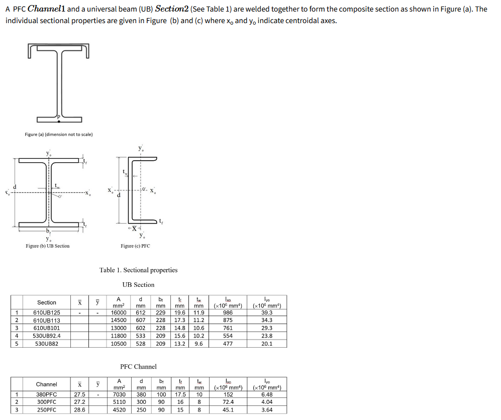
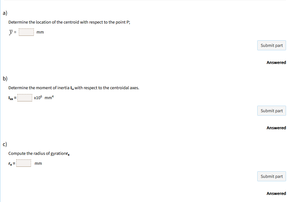


A PFC Channell and a universal beam (UB) Section2 (See Table 1) are welded together to form the composite section as shown in Figure (a). The individual sectional properties are given in Figure (b) and (c) where x, and yo indicate centroidal axes. Figure (a) (dimension not to scale) y. Figure (b) UB Section Figure (c) PFC Table 1. Sectional properties UB Section Section X y d br mm2 mm mm mm mm (x105 mm4) [x105 mm4) 610UB125 16000 229 19.6 11.9 986 39.3 610UB113 14500 607 228 17.3 11.2 875 34.3 IA W N 610UB101 13000 602 228 14.8 10.6 761 29.3 530UB92.4 1800 533 209 15.6 10.2 654 23.8 530UB82 10500 209 13.2 9.6 477 20.1 PFC Channel Channel X y A lyo mm2 mm mm mm mm (x105 mm) (x105 mm4) 380PFC 27.5 7030 380 100 17.5 10 152 6.48 N - 300PFC 27.2 5110 300 90 16 8 72.4 4.04 250PFC 28.6 4520 250 90 15 8 45.1 3.64a Determine the location of the centroid with respect to the point P; V= mm Submit part Answered b) Determine the moment of inertia I. with respect to the centroidal axes. | x105 mm4 Submit part Answered c) Compute the radius of gyrationrx mm Submit part Answered
Step by Step Solution
There are 3 Steps involved in it

Get step-by-step solutions from verified subject matter experts