

Question: A process tank with an input pump, heater, and drain valve, is used for liquid heating applications commonly found in the chemical and food processing
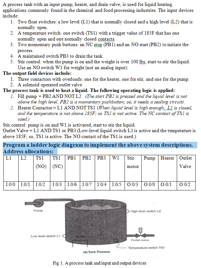
A process tank with an input pump, heater, and drain valve, is used for liquid heating applications commonly found in the chemical and food processing industries. The input devices include 1. Two float switches: a low level (L1) that is normally closed and a high level (L2) that is 2. 3. 4. normally open A temperature switch: one switch (TS1) with a trigger value of 185F that has one normally open and one normally closed contacts Two momentary push buttons: an NC stop (PB1) and an NO start (PB2) to initiate the processS A maintained switch PB3 to drain the tank. Stir control: when the pump is on and the weight is over 100 lbs, start to stir the liquid Use an NO switch W1 for weight (not an analog input) 5. The output field devices include 1. Three contactors with overloads: one for the heater, one for stir, and one for the pump 2. A solenoid operated outlet valve 1. Fill pump - PB2 AND NOTL2 (The start PB2 is pressed and the liquid level is not 2. The process tank is used to heat a liquid. The following operating logic is applied above the high level. PB2 is a momentary pushbutton; so, it needs a sealing circuit) Heater Contactor= L1 AND NOT TSI (When liquid level is high enough, Ll is closed, and the temperature is not above 185F; so TSl is not active. The NC contact of TSI is used) Stir control: pump is on and W1 is activated, start to stir the liquid Outlet Valve = L 1 AND TSI or PB3 (Low-level liquid switch L1 is active and the temperature is above 185F; so, TS1 is active. The NO contact of the TS1 is used.) Program a ladder logic diagram to implement the above system descriptions. Address allocations: L1L2TS1 TS1 P PB2 PB3W1Stir PumpHeater Outlet (No) Nc) Valve motor Pump High level switch L2 Low lovel switch L1 Temperature switch TS (a) Tank Process Fig 1. A process tank and input and output devices A process tank with an input pump, heater, and drain valve, is used for liquid heating applications commonly found in the chemical and food processing industries. The input devices include 1. Two float switches: a low level (L1) that is normally closed and a high level (L2) that is 2. 3. 4. normally open A temperature switch: one switch (TS1) with a trigger value of 185F that has one normally open and one normally closed contacts Two momentary push buttons: an NC stop (PB1) and an NO start (PB2) to initiate the processS A maintained switch PB3 to drain the tank. Stir control: when the pump is on and the weight is over 100 lbs, start to stir the liquid Use an NO switch W1 for weight (not an analog input) 5. The output field devices include 1. Three contactors with overloads: one for the heater, one for stir, and one for the pump 2. A solenoid operated outlet valve 1. Fill pump - PB2 AND NOTL2 (The start PB2 is pressed and the liquid level is not 2. The process tank is used to heat a liquid. The following operating logic is applied above the high level. PB2 is a momentary pushbutton; so, it needs a sealing circuit) Heater Contactor= L1 AND NOT TSI (When liquid level is high enough, Ll is closed, and the temperature is not above 185F; so TSl is not active. The NC contact of TSI is used) Stir control: pump is on and W1 is activated, start to stir the liquid Outlet Valve = L 1 AND TSI or PB3 (Low-level liquid switch L1 is active and the temperature is above 185F; so, TS1 is active. The NO contact of the TS1 is used.) Program a ladder logic diagram to implement the above system descriptions. Address allocations: L1L2TS1 TS1 P PB2 PB3W1Stir PumpHeater Outlet (No) Nc) Valve motor Pump High level switch L2 Low lovel switch L1 Temperature switch TS (a) Tank Process Fig 1. A process tank and input and output devices
Step by Step Solution
There are 3 Steps involved in it

Get step-by-step solutions from verified subject matter experts