

Question: A sample 10-bus power network is shown in Figure 1 and its data are listed in Table 1 and Table 2. All impedance data are
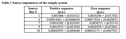
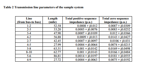
A sample 10-bus power network is shown in Figure 1 and its data are listed in Table 1 and Table 2. All impedance data are given in per unit with a base voltage of 500 KV and base voltampere of 100 MVA. The positive- and negative-sequence impedances are assumed to be equal.
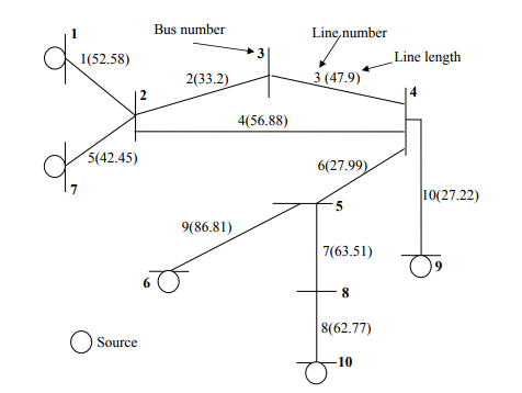
Figure 1. A sample 10-bus power system
In all of the problems below, it is assumed that the pre-fault voltage at each node is 1.0 p.u., which is a common assumption in short circuit analysis for transmission systems.
1. Develop a program to formulate the Zbus of the network. To simplify your task, you may manually enter the network data in your program.
2. Suppose that there is a three phase fault with fault resistance of 10 ohms at node 2, find out the phase voltage at each node during the fault. You are required to develop a computer program to do this. Make sure to convert the fault resistance to per unit value if all your other quantities are in per unit.
Bus number Line,number 1(52.58) Line length 2(33.2) 3 (47.9) 4(56.88) 5(42.45) 6(27.99) 10(27.22) 9(86.81) 7(63.51) 6 8 8(62.77) Source Bus number Line,number 1(52.58) Line length 2(33.2) 3 (47.9) 4(56.88) 5(42.45) 6(27.99) 10(27.22) 9(86.81) 7(63.51) 6 8 8(62.77) Source
Step by Step Solution
There are 3 Steps involved in it

Get step-by-step solutions from verified subject matter experts