

Question: Part I: Power Flow Calculations 1. For the single line diagram that is shown in Figure 1, below, convert all positive-sequence impedance, load, and voltage
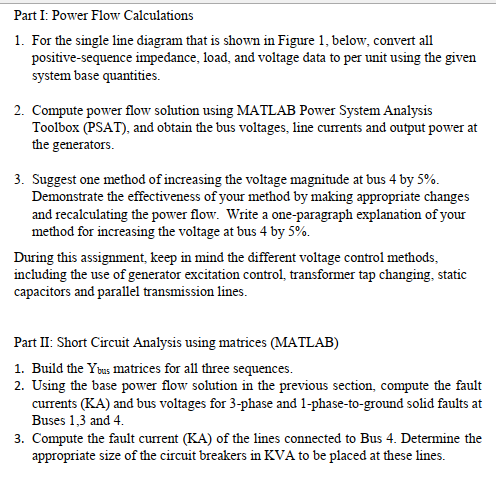
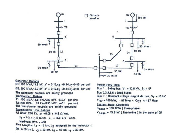
Part I: Power Flow Calculations 1. For the single line diagram that is shown in Figure 1, below, convert all positive-sequence impedance, load, and voltage data to per unit using the given system base quantities. 2. Compute power flow solution using MATLAB Power System Analysis Toolbox (PSAT), and obtain the bus voltages, line currents and output power at the generators. 3. Suggest one method of increasing the voltage magnitude at bus 4 by 5%. Demonstrate the effectiveness of your method by making appropriate changes and recalculating the power flow. Write a one-paragraph explanation of your method for increasing the voltage at bus 4 by 5%. During this assignment, keep in mind the different voltage control methods, including the use of generator excitation control, transformer tap changing, static capacitors and parallel transmission lines. Part II: Short Circuit Analysis using matrices (MATLAB) 1. Build the Ybus matrices for all three sequences. 2. Using the base power flow solution in the previous section, compute the fault currents (KA) and bus voltages for 3-phase and 1-phase-to-ground solid faults at Buses 1,3 and 4. 3. Compute the fault current (KA) of the lines connected to Bus 4. Determine the appropriate size of the circuit breakers in KVA to be placed at these lines. GI Circuit Breaker 180 MM otte TI I2NW 30 Hvar D 30 Hvar 50 MM 50 L1 L4 30 Hvar L2 L3 50 MM 30 Hvar 30 Hvar SO'M 50 MM Generator Ratings G1: 100 MVA 13.8 kv, x - 0.12,42 -0.14,X0-0.05 per unit Q2: 200 MVA 15.0 kV, x- 0.12,x2 -0.14,X0-0.05 per unit The generator noutrals are solidly grounded Transformer Ratings T1: 100 MVA 13.8 KVA/230 kVY, X-0.1 per unit T2: 200 MVA, 15 KVA 230 kVY, X-0.1 per unit The transformer neutrals are solidly grounded Transmission Line Ratings All Lines: 230 kV, 24 -0.08 - 10.5 g/km. 20 - 0.2 +1.5 Alkm, 91 - 13.3 E-6 Skm, Maximum MVA - 400 Line Lengths: 14 - 15 km, 12 assigned by the instructor 20 to 50 km), L - 40 km, 4 - 15 km, Ls - 50 km. Power Flow Data Bus 1 : Swing bus. V4 - 13.8 kV, aq - 00 Bus 2,3,4,5,6 : Load buses Bus 7: Constant voltage magnitude bus, V7 - 15 kV PG7 - 180 MW, - 87 Mvar
Step by Step Solution
There are 3 Steps involved in it

Get step-by-step solutions from verified subject matter experts