

Question: A single - phase full - wave ac controller shown in Fig. P 3 . 1 is used to control the power from a 2
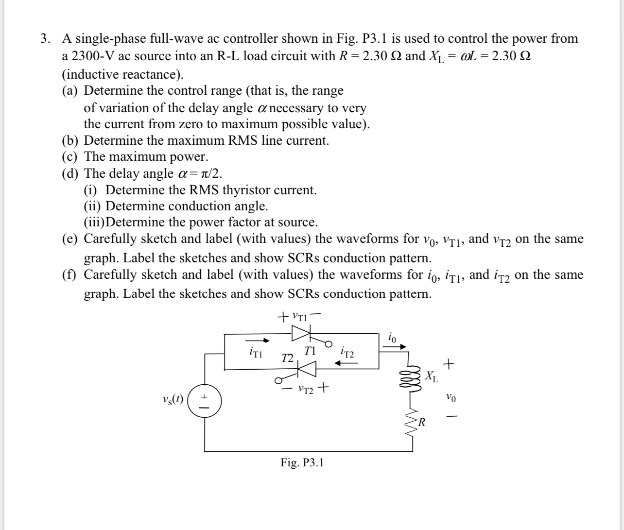
A singlephase fullwave ac controller shown in Fig. P is used to control the power from a ac source into an RL load circuit with and inductive reactance
a Determine the control range that is the range of variation of the delay angle necessary to very the current from zero to maximum possible value
b Determine the maximum RMS line current.
c The maximum power.
d The delay angle
i Determine the RMS thyristor current.
ii Determine conduction angle.
iiiDetermine the power factor at source.
e Carefully sketch and label with values the waveforms for and on the same graph. Label the sketches and show SCRs conduction pattern.
f Carefully sketch and label with values the waveforms for and on the same graph. Label the sketches and show SCRs conduction pattern.
Step by Step Solution
There are 3 Steps involved in it
1 Expert Approved Answer
Step: 1 Unlock

Question Has Been Solved by an Expert!
Get step-by-step solutions from verified subject matter experts
Step: 2 Unlock
Step: 3 Unlock