

Question: A sketch map with contour lines at 25m intervals is provided. The red lines on the sketch map show two possible new road alignments (X
A sketch map with contour lines at 25m intervals is provided. The red lines on the sketch map show two possible new road alignments (X and Y) to cross a river and climb to the flatter high ground. The bearing and distance of each straight is shown and the radius proposed for each of the horizontal curves is also shown. The green lines are the ends of existing roads which need to be joined. These roads are on the natural surface. The land below the 100m contour is unoccupied bush land while above the 100m contour is developed farmland in private ownership.
The proposed routes have been drawn by bureaucrats, where their main aim is to avoid existing houses. Where possible the road should follow the natural surface minimising cut and fill. The proposal has now been passed to the Engineering Department to assess the two possible routes. Your task consists of the following four parts.
Part 1(Done):Using the horizontal curve data shown (where R is the radius of each curve) calculate the length of each bypass (to 1 decimal place). Also list the chainages of each T.P. along each road. It is not necessary to show all of your working/calculations, but it would be good to show the results of individual calculations.
Part 2:
Question: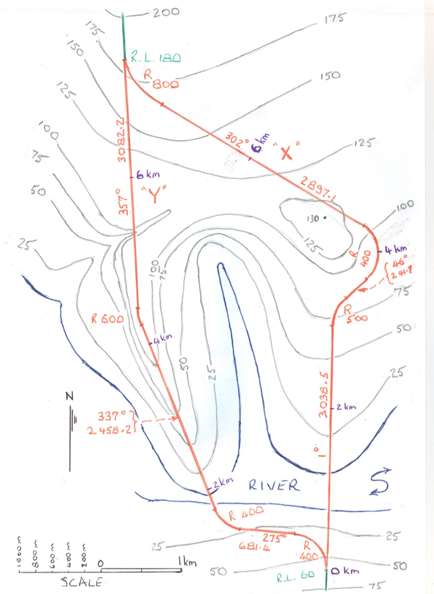
- Some members of council have asked for clarification about the proposed road options as they do not understand the plan provided.
For each road, section by section, as shown at the bottom of the page, describe the roads horizontal alignment in a sentence or two. In a few paragraphs, describe the longitudinal slopes of the natural surface along each section. Explain where you would expect substantial vertical curves to be needed in the road design by suggesting appropriate I.P. locations. Further, you must draw attention to any structures that would be needed, such as bridges and bridge approaches. Also identify any areas where you would expect large depths of cut or fill to occur, or difficulties in meeting the design criteria due to the grade of the land.
2. While the entire road will need to eventually have a final accurate survey completed, for those areas that you have mentioned in part 2 above, to assist with assessing each roads suitability, more detailed survey work on site will be undertaken immediately. As part of this section, you must suggest possible R.L.s for the decks of any bridges and the impacts that those R.L.s will have on the road design. As part of this assessment process you may also wish to recommend areas to investigate for possible minor horizontal deviations (for example, less then 800m in length and less than 150m sideways deviation) to be included in such survey work if you feel it would help the road design. Please describe what information each of those site surveys should obtain.
Road X
Section 1: Ch 00 to T.P.2 (the end of the 500m Horizontal Curve)
Horizontal Alignment
Vertical Alignment
Extra Surveying Work Needed and any areas for special investigation
Section 2: T.P.2 to the end of the road
Horizontal Alignment
Vertical Alignment
Extra Surveying Work Needed and any areas for special investigation
Road Y
Section 1: Ch 00 to T.P. 3 (the start of the 600m Horizontal Curve)
Horizontal Alignment
Vertical Alignment
Extra Surveying Work Needed and any areas for special investigation
Section 2: T.P.3 to Ch 5km
Horizontal Alignment
Vertical Alignment
Extra Surveying Work Needed and any areas for special investigation
Section 3: Ch 5km to the end of Road Y
Horizontal Alignment
Vertical Alignment
Extra Surveying Work Needed and any areas for special investigation
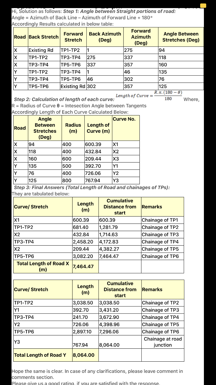
337 Hi, Solution as follows: Step 1: Angle between Straight portions of road: Angle = Azimuth of Back Line - Azimuth of Forward Line + 180 Accordingly Results calculated in below table: Forward Forward Back Azimuth Road Back Stretch Angle Between Stretch Azimuth (Deg) Stretches (Deg) (Deg) X Existing Rd TP1-TP2 275 94 X TP1-TP2 TP3-TP4 275 337 118 X TP3-TP4 TP5-TP6 357 160 Y TP1-TP2 TP3-TP4 1 46 135 Y TP3-TP4 TP5-TP6 146 302 76 Y TP5-TP6 Existing Rd 302 357 125 R.T. (180 - Length of Curve = Step 2: Calculation of length of each curve: 180 Where, R = Radius of Curve @ = Intesection Angle between Tangents Accordingly Length of Each Curve Calculated Below: Angle Curve No. Between Radius Length of Road Stretches (m) Curve (m) (Deg) X 94 400 600.39 X1 X 118 400 432.84 X2 X 160 600 209.44 X3 Y 135 500 392.70 Y1 Y 76 400 726.06 Y2 Y 125 800 767.94 Y3 Step 3: Final Answers (Total Length of Road and chainages of TPs): They are tabulated below: Cumulative Length Curve/ Stretch Distance from Remarks (m) start X1 600.39 600.39 Chainage of TP1 TP1-TP2 681.40 1,281.79 Chainage of TP2 X2 432.84 1,714.63 Chainage of TP3 TP3-TP4 2,458.20 4,172.83 Chainage of TP4 X2 209.44 4,382.27 Chainage of TP5 TP5-TP6 3,082.20 7,464.47 Chainage of TP6 Total Length of Road X 7,464.47 (m) Curve/ Stretch Length (m) TP1-TP2 Y1 TP3-TP4 Y2 TP5-TP6 3,038.50 392.70 241.70 726.06 2,897.10 Cumulative Distance from Remarks start 3,038.50 Chainage of TP2 3,431.20 Chainage of TP3 3,672.90 Chainage of TP4 4,398.96 Chainage of TP5 7,296.06 Chainage of TP6 Chainage at road 8,064.00 junction Y3 767.94 Total Length of Road Y 8,064.00 Hope the same is clear. In case of any clarifications, please leave comment in comments section. Please give us a good rating if you are satisfied with the response 200 175 175 150 R. 1.180 Ro .800 150 125 100 302 28.08 125 75 .6km 2897.1 50 357 "Y 100 130 25 .4 km Coo 001 (241-7 75 R GOD 500 50 44 km 25 N N 3038.5 42 km 33707 2.458.2 -3 km RIVER S R 400 275 681.4 25 E 25 R 400 Ikm 50 okm 50 SCALE RoL. 60 75 337 Hi, Solution as follows: Step 1: Angle between Straight portions of road: Angle = Azimuth of Back Line - Azimuth of Forward Line + 180 Accordingly Results calculated in below table: Forward Forward Back Azimuth Road Back Stretch Angle Between Stretch Azimuth (Deg) Stretches (Deg) (Deg) X Existing Rd TP1-TP2 275 94 X TP1-TP2 TP3-TP4 275 337 118 X TP3-TP4 TP5-TP6 357 160 Y TP1-TP2 TP3-TP4 1 46 135 Y TP3-TP4 TP5-TP6 146 302 76 Y TP5-TP6 Existing Rd 302 357 125 R.T. (180 - Length of Curve = Step 2: Calculation of length of each curve: 180 Where, R = Radius of Curve @ = Intesection Angle between Tangents Accordingly Length of Each Curve Calculated Below: Angle Curve No. Between Radius Length of Road Stretches (m) Curve (m) (Deg) X 94 400 600.39 X1 X 118 400 432.84 X2 X 160 600 209.44 X3 Y 135 500 392.70 Y1 Y 76 400 726.06 Y2 Y 125 800 767.94 Y3 Step 3: Final Answers (Total Length of Road and chainages of TPs): They are tabulated below: Cumulative Length Curve/ Stretch Distance from Remarks (m) start X1 600.39 600.39 Chainage of TP1 TP1-TP2 681.40 1,281.79 Chainage of TP2 X2 432.84 1,714.63 Chainage of TP3 TP3-TP4 2,458.20 4,172.83 Chainage of TP4 X2 209.44 4,382.27 Chainage of TP5 TP5-TP6 3,082.20 7,464.47 Chainage of TP6 Total Length of Road X 7,464.47 (m) Curve/ Stretch Length (m) TP1-TP2 Y1 TP3-TP4 Y2 TP5-TP6 3,038.50 392.70 241.70 726.06 2,897.10 Cumulative Distance from Remarks start 3,038.50 Chainage of TP2 3,431.20 Chainage of TP3 3,672.90 Chainage of TP4 4,398.96 Chainage of TP5 7,296.06 Chainage of TP6 Chainage at road 8,064.00 junction Y3 767.94 Total Length of Road Y 8,064.00 Hope the same is clear. In case of any clarifications, please leave comment in comments section. Please give us a good rating if you are satisfied with the response 200 175 175 150 R. 1.180 Ro .800 150 125 100 302 28.08 125 75 .6km 2897.1 50 357 "Y 100 130 25 .4 km Coo 001 (241-7 75 R GOD 500 50 44 km 25 N N 3038.5 42 km 33707 2.458.2 -3 km RIVER S R 400 275 681.4 25 E 25 R 400 Ikm 50 okm 50 SCALE RoL. 60 75
Step by Step Solution
There are 3 Steps involved in it

Get step-by-step solutions from verified subject matter experts