

Question: A synchronous logic circuit has one SR flip-flop, one T flip-flop, and one input. There is no output at the circuit. The input is represented
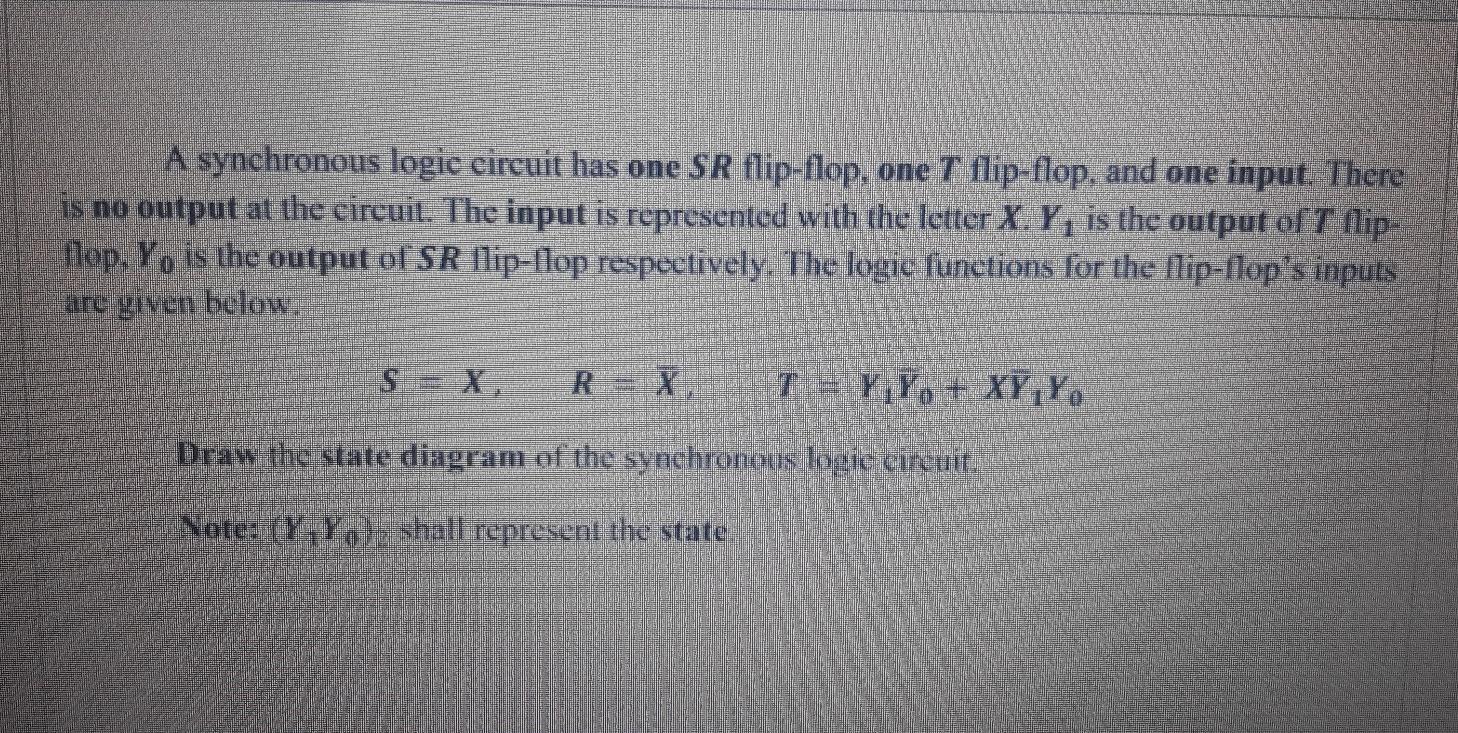
A synchronous logic circuit has one SR flip-flop, one T flip-flop, and one input. There is no output at the circuit. The input is represented with the letter X, Y, is the output off lip- llop, Yo is the output of SR llip-flop respectively. The logic functions for the lip-flop's inputs are given below R = X Ta Y Yo + XY,Y. Draw the state diagram of the synchronous logic circuit. Note: (Y, Y , shall represent the state
Step by Step Solution
There are 3 Steps involved in it
1 Expert Approved Answer
Step: 1 Unlock

Question Has Been Solved by an Expert!
Get step-by-step solutions from verified subject matter experts
Step: 2 Unlock
Step: 3 Unlock