

Question: The given State Diagram represents a circuit that has two Flip-Flops (A and B), one input (X) and one output (Y). 00 1/0 0/0 1/0
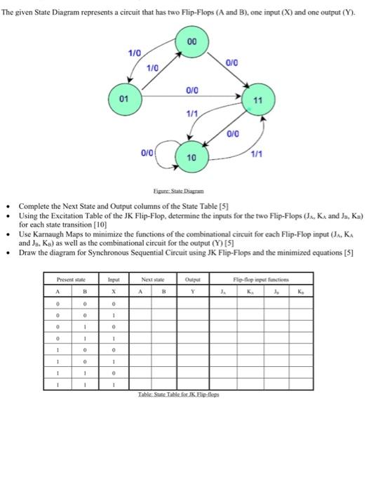
The given State Diagram represents a circuit that has two Flip-Flops (A and B), one input (X) and one output (Y). 00 1/0 0/0 1/0 0/0 01 11 1/1 0/0 0101 10 1/1 Figure: State Diagstum Complete the Next State and Output columns of the State Table [5] Using the Excitation Table of the JK Flip-Flop, determine the inputs for the two Flip-Flops (J, K, and Ja, Ka) for each state transition [10] Use Karnaugh Maps to minimize the functions of the combinational circuit for each Flip-Flop input (J., K and Jo, Ka) as well as the combinational circuit for the output (Y) [5] Draw the diagram for Synchronous Sequential Circuit using JK Flip-Flops and the minimized equations [5] Presente Input Next state Flip-top input functions Output Y A B A B 0 0 0 0 1 0 1 0 0 1 1 1 0 0 1 1 1 0 1 1 ! 1 Table State Table for Flip-flops
Step by Step Solution
There are 3 Steps involved in it

Get step-by-step solutions from verified subject matter experts