

Question: A T flip-flop is a 1-bit synchronous storage component alternative to the D flip-flop, with a slightly different interface. Besides the clock signal and an
A T flip-flop is a 1-bit synchronous storage component alternative to the D flip-flop, with a slightly different interface. Besides the clock signal and an optional clear signal, the T flip-flop has one input t to synchronously control the state of the flip-flop, as follows:
When T is 0, the flip-flop does not change its state.
When T is 1, the flip-flop inverts its current value (0 becomes 1, and 1 becomes 0).
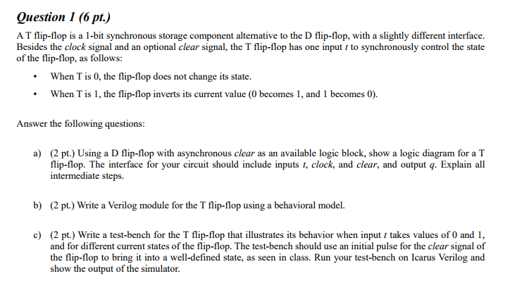
Question 1 (6 pt.) A T flip-flop is a 1-bit synchronous storage component alternative to the D flip-flop, with a slightly different interface Besides the clock signal and an optional clear signal, the T flip-flop has one input to synchronously control the state of the flip-flop, as follows: When T is 0, the flip-flop does not change its state. When T is 1, the flip-flop inverts its current value (0 becomes 1, and 1 becomes 0). Answer the following questions (2 pt.) Using a D flip-flop with asynchronous clear as an available logic block, show a logic diagram for a T flip-flop. The interface for your circuit should include inputs t, clock, and clear, and output q. Explain all intermediate steps a) b) (2 pt.) Write a Verilog module for the T flip-flop using a behavioral model. (2 pt.) Write a test-bench for the T flip-flop that illustrates its behavior when input takes values of 0 and 1, and for different current states of the flip-flop. The test-bench should use an initial pulse for the clear signal of the flip-flop to bring it into a well-defined state, as seen in class. Run your test-bench on Icarus Verilog and show the output of the simulator. c) Question 1 (6 pt.) A T flip-flop is a 1-bit synchronous storage component alternative to the D flip-flop, with a slightly different interface Besides the clock signal and an optional clear signal, the T flip-flop has one input to synchronously control the state of the flip-flop, as follows: When T is 0, the flip-flop does not change its state. When T is 1, the flip-flop inverts its current value (0 becomes 1, and 1 becomes 0). Answer the following questions (2 pt.) Using a D flip-flop with asynchronous clear as an available logic block, show a logic diagram for a T flip-flop. The interface for your circuit should include inputs t, clock, and clear, and output q. Explain all intermediate steps a) b) (2 pt.) Write a Verilog module for the T flip-flop using a behavioral model. (2 pt.) Write a test-bench for the T flip-flop that illustrates its behavior when input takes values of 0 and 1, and for different current states of the flip-flop. The test-bench should use an initial pulse for the clear signal of the flip-flop to bring it into a well-defined state, as seen in class. Run your test-bench on Icarus Verilog and show the output of the simulator. c)
Step by Step Solution
There are 3 Steps involved in it

Get step-by-step solutions from verified subject matter experts