

Question: A template file has been provided for you called reg.circ, which you can start with and then modify. You should not move the components given
A template file has been provided for you called reg.circ, which you can start with and then modify. You should not move the components given in the template. The circuit needs to be done on logisim-evloution. Below is the template reg.circ:
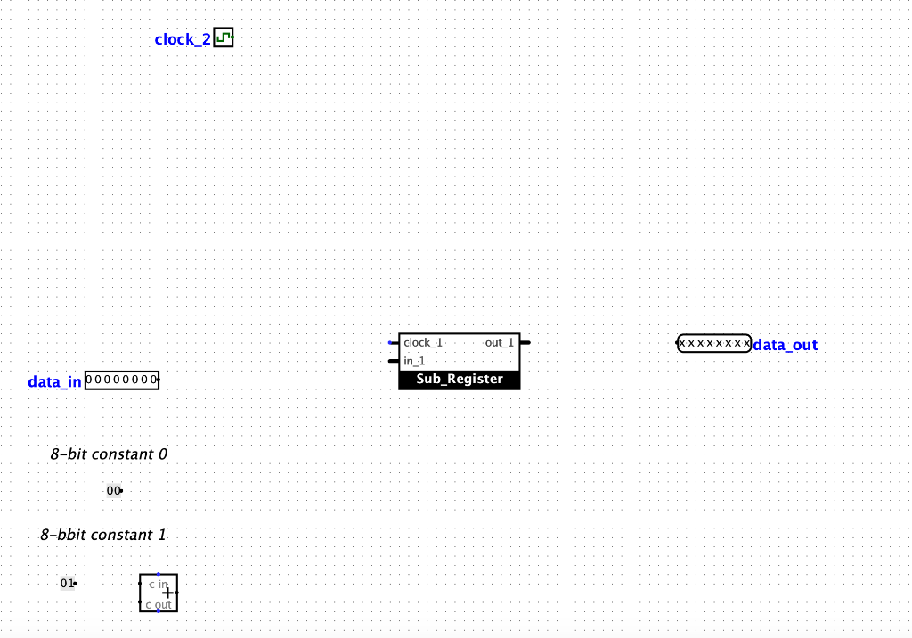
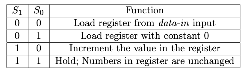
There are two parts to this question. In the first part, you will design a register using 8 rising edge triggered D flip-flops. Use the template reg.circ file provided to design your register such that the input bits in 1 are copied onto the output bits out 1 when clock 1 is enabled. Name this circuit Sub Register'. In the second part, you will design a register using the Sub Register circuit built in the first part. Begin by adding a new circuit to your project and name it Four_Input_Register'. A copy of your sub-register from the first part will be used as a basis for this circuit. The register will have three input sources: an external data-in input an 8-bit constant input initialized to zero, and the output of an Adder that increments the register by adding 1 to the current value in the register. Add a single clock bit to control the operation of the clock. Finally, add a multiplexer with 8 data bits and 2 select bits. Add a 2-bit input to connect to the select input of the multiplexer. The roles of the select bits are described in the table below. The operation is controlled by the clock input. Si So Oo 0 1 1 0 | 1 | 1 Function Load register from data-in input Load register with constant 0 Increment the value in the register Hold; Numbers in register are unchanged clock_20 . . . . . . . . . . . . . . . . . . . . . . . . . . . . . . . . . . . . . . . . . . . . . . . . . . . . . . . . . . . . . . . . . . . . . . . . . . . . . .. . . . . . . . . .. . .... . .. clock 1 out 1 . . . . . . .. .. . X X X X X X X X d ata'ou t . . . . . . . . . . . . . . . . . . . . . . . . . . . . . . . . . in .1 . . . . . . . . . data_in 00000000 0 00 . . . . . . . . . . . . . . . . . . . . . . . Sub Register . . . .& 8-bit constant 0 -h it con s tan t . . . . . . . . . . . . . . . . . . . .0 0 . . . . . . . . . . . . . . . .. 8-bbit constant 1 b bit constant I. . . . . . . . . . . . . . . . . . . . . . . . . . . . . . . . . . . . . . . . . . . . . . . . . . . . . . . . . . . . . . . . . . . . . . . !!! . . in . . . . . . . . . . . . . . . . . . . . . . . . . . . . . . . . . . . . . . . . . . . . . . . . . . . . . . . . . . . . . . . . . . . . . . . . . . . . . . I cout There are two parts to this question. In the first part, you will design a register using 8 rising edge triggered D flip-flops. Use the template reg.circ file provided to design your register such that the input bits in 1 are copied onto the output bits out 1 when clock 1 is enabled. Name this circuit Sub Register'. In the second part, you will design a register using the Sub Register circuit built in the first part. Begin by adding a new circuit to your project and name it Four_Input_Register'. A copy of your sub-register from the first part will be used as a basis for this circuit. The register will have three input sources: an external data-in input an 8-bit constant input initialized to zero, and the output of an Adder that increments the register by adding 1 to the current value in the register. Add a single clock bit to control the operation of the clock. Finally, add a multiplexer with 8 data bits and 2 select bits. Add a 2-bit input to connect to the select input of the multiplexer. The roles of the select bits are described in the table below. The operation is controlled by the clock input. Si So Oo 0 1 1 0 | 1 | 1 Function Load register from data-in input Load register with constant 0 Increment the value in the register Hold; Numbers in register are unchanged clock_20 . . . . . . . . . . . . . . . . . . . . . . . . . . . . . . . . . . . . . . . . . . . . . . . . . . . . . . . . . . . . . . . . . . . . . . . . . . . . . .. . . . . . . . . .. . .... . .. clock 1 out 1 . . . . . . .. .. . X X X X X X X X d ata'ou t . . . . . . . . . . . . . . . . . . . . . . . . . . . . . . . . . in .1 . . . . . . . . . data_in 00000000 0 00 . . . . . . . . . . . . . . . . . . . . . . . Sub Register . . . .& 8-bit constant 0 -h it con s tan t . . . . . . . . . . . . . . . . . . . .0 0 . . . . . . . . . . . . . . . .. 8-bbit constant 1 b bit constant I. . . . . . . . . . . . . . . . . . . . . . . . . . . . . . . . . . . . . . . . . . . . . . . . . . . . . . . . . . . . . . . . . . . . . . . !!! . . in . . . . . . . . . . . . . . . . . . . . . . . . . . . . . . . . . . . . . . . . . . . . . . . . . . . . . . . . . . . . . . . . . . . . . . . . . . . . . . I cout
Step by Step Solution
There are 3 Steps involved in it

Get step-by-step solutions from verified subject matter experts