

Question: 1 An 8-bit Shift Register (30 marks) Design an 8-bit shift register with output bits A7 A6.A5.A4A3 A2Ai Ao. Each bit A is repre- sented
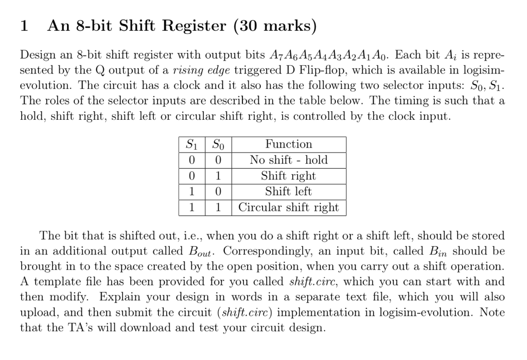
1 An 8-bit Shift Register (30 marks) Design an 8-bit shift register with output bits A7 A6.A5.A4A3 A2Ai Ao. Each bit A is repre- sented by the Q output of a rising edge triggered D Flip-flop, which is available in logisim- evolution. The circuit has a clock and it also has the following two selector inputs: So, S1. The roles of the selector inputs are described in the table below. The timing is such that a hold, shift right, shift left or circular shift right, is controlled by the clock input. 0 Function 0 No shift - hold Shift right Shift left Circular shift right 11 The bit that is shifted out, i.e., when you do a shift right or a shift left, should be stored in an additional output called Bout. Correspondingly, an input bit, called Bin should be brought in to the space created by the open position, when you carry out a shift operation A template file has been provided for you called shift.circ, which you can start with and then modify. Explain your design in words in a separate text file, which you will also upload, and then submit the circuit (shift.circ) implementation in logisim-evolution. Note that the TA's will download and test your circuit design. 1 An 8-bit Shift Register (30 marks) Design an 8-bit shift register with output bits A7 A6.A5.A4A3 A2Ai Ao. Each bit A is repre- sented by the Q output of a rising edge triggered D Flip-flop, which is available in logisim- evolution. The circuit has a clock and it also has the following two selector inputs: So, S1. The roles of the selector inputs are described in the table below. The timing is such that a hold, shift right, shift left or circular shift right, is controlled by the clock input. 0 Function 0 No shift - hold Shift right Shift left Circular shift right 11 The bit that is shifted out, i.e., when you do a shift right or a shift left, should be stored in an additional output called Bout. Correspondingly, an input bit, called Bin should be brought in to the space created by the open position, when you carry out a shift operation A template file has been provided for you called shift.circ, which you can start with and then modify. Explain your design in words in a separate text file, which you will also upload, and then submit the circuit (shift.circ) implementation in logisim-evolution. Note that the TA's will download and test your circuit design
Step by Step Solution
There are 3 Steps involved in it

Get step-by-step solutions from verified subject matter experts