

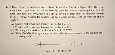
Question: A three - phase transmission line is shown in one - line format in Figure 1 1 . 8 . The buses at each end,
A threephase transmission line is shown in oneline format in Figure The buses at each end, represented as voltage sources, haye the same voltage magnitude; kV RMS lineline. For now, model the line as having an impedance to balanced currents of Assume the sending end has a plase advance over the receiving end of angle
a What is real power flow through the line for
b What is real power flow through the line for
c What angle $ results in a real power flow of MW
d With MW tlowing through the line, what is reactive power at the sending and receiving ends?
Step by Step Solution
There are 3 Steps involved in it
1 Expert Approved Answer
Step: 1 Unlock

Question Has Been Solved by an Expert!
Get step-by-step solutions from verified subject matter experts
Step: 2 Unlock
Step: 3 Unlock