

Question: A three-bus system is described by the following input data: u) An MVA MVAr Slack PV Load 1.0 05 200 200 0.2 0.1 0.15 MVA
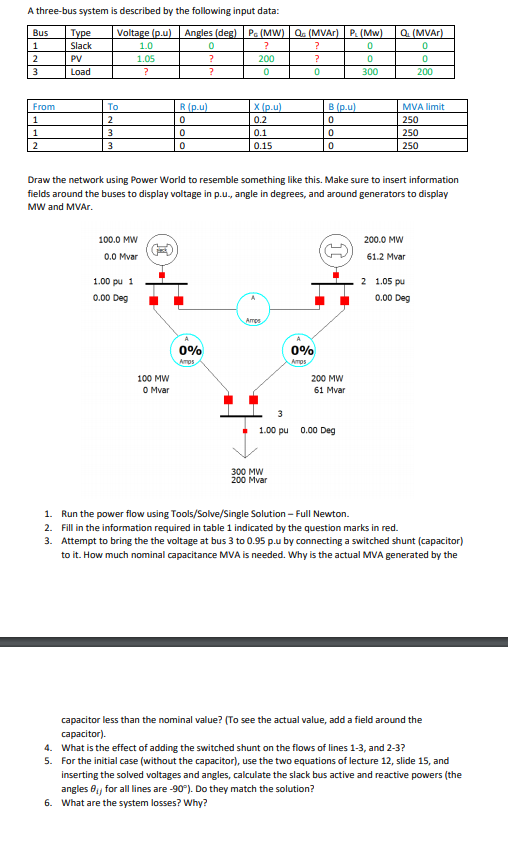
A three-bus system is described by the following input data: u) An MVA MVAr Slack PV Load 1.0 05 200 200 0.2 0.1 0.15 MVA limit 250 250 250 Draw the network using Power World to resemble something like this. Make sure to insert information fields around the buses to display voltage in p.u., angle in degrees, and around generators to display MW and MVAr 100.0 MW 200.0 MW 0.0 Mvar 61.2 Mvar 2 1.05 pu 1.00 pu1 0.00 Deg 0.00 Deg 090 090 100 MW 0 Mvar 200 MW 61 Mvar 1.00 pu 0.00 Deg 300 MW 200 Mvar 1. 2. 3. Run the power flow using Tools/Solve/Single Solution- Full Newton. Fill in the information required in table 1 indicated by the question marks in red. Attempt to bring the the voltage at bus 3 to 0.95 .u by connecting a switched shunt (capacitor) to it. How much nominal capacitance MVA is needed. Why is the actual MVA generated by the capacitor less than the nominal value? (To see the actual value, add a field around the capacitor). What is the effect of adding the switched shunt on the flows of lines 1-3, and 2-3? For the initial case (without the capacitor), use the two equations of lecture 12, slide 15, and inserting the solved voltages and angles, calculate the slack bus active and reactive powers (the angles for all lines are-90). Do they match the solution? What are the system losses? Why? 4. 5. 6
Step by Step Solution
There are 3 Steps involved in it

Get step-by-step solutions from verified subject matter experts