

Question: Consider a three-bus power system with the single-line diagram shown in Fig. 1. In the three-bus system, Bus 1 is the slack bus where
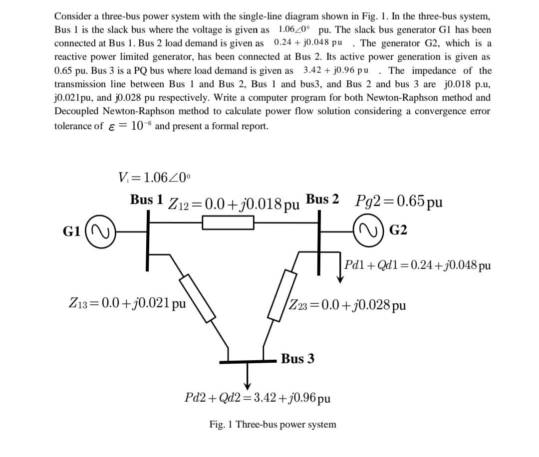
Consider a three-bus power system with the single-line diagram shown in Fig. 1. In the three-bus system, Bus 1 is the slack bus where the voltage is given as 1.06/0 pu. The slack bus generator Gl has been connected at Bus 1. Bus 2 load demand is given as 0.24+ j0.048 pu The generator G2, which is a reactive power limited generator, has been connected at Bus 2. Its active power generation is given as 0.65 pu. Bus 3 is a PQ bus where load demand is given as 3.42 + j0.96 pu. The impedance of the transmission line between Bus 1 and Bus 2, Bus 1 and bus3, and Bus 2 and bus 3 are j0.018 p.u, j0.021pu, and j0.028 pu respectively. Write a computer program for both Newton-Raphson method and Decoupled Newton-Raphson method to calculate power flow solution considering a convergence error tolerance of = 10 and present a formal report. G1 ( V=1.06/0 Bus 1 Z12=0.0+j0.018 pu Z13 0.0+j0.021 pu Bus 2 Pg2=0.65 pu (~) G2 Z23=0.0+j0.028 pu Bus 3 Pd1+Qd1=0.24+j0.048 pu Pd2 + Qd2=3.42 +j0.96 pu Fig. 1 Three-bus power system
Step by Step Solution
3.50 Rating (147 Votes )
There are 3 Steps involved in it
I can help you outline the basic structure of the computer program for both the NewtonRaphson method ... View full answer

Get step-by-step solutions from verified subject matter experts