

Question: A truss is shown in the figure. Support E is pinned and Support A is a roller. All theThe beam is depicted in the figure.
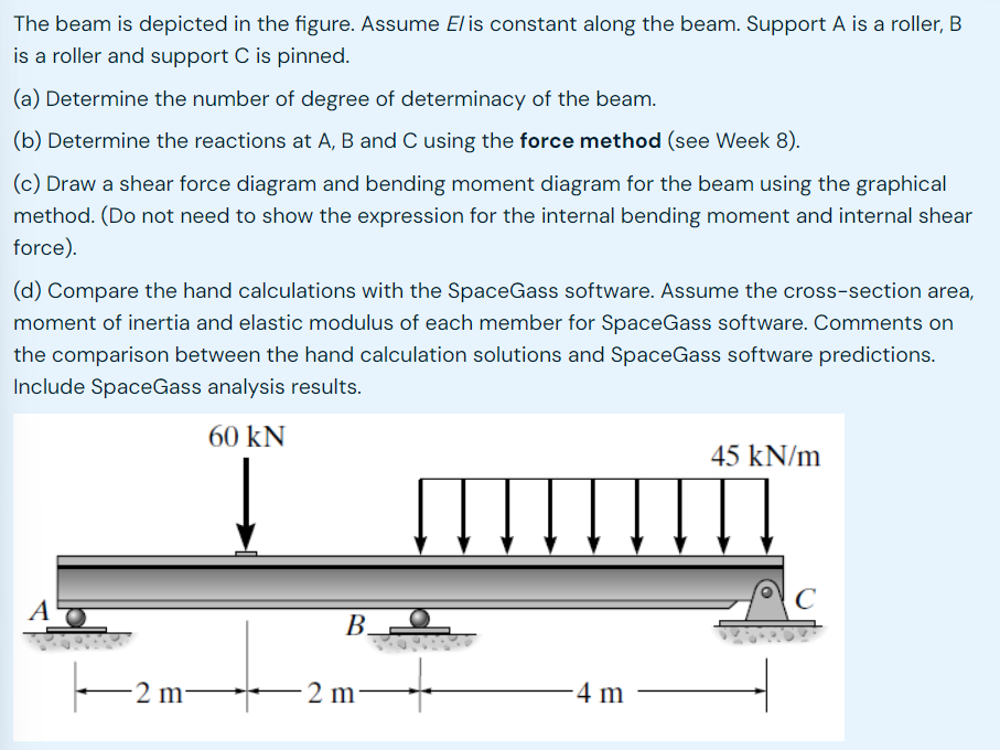
A truss is shown in the figure. Support is pinned and Support is a roller. All theThe beam is depicted in the figure. Assume l is constant along the beam. Support A is a roller, B
is a roller and support is pinned.
a Determine the number of degree of determinacy of the beam.
b Determine the reactions at A B and C using the force method see Week
c Draw a shear force diagram and bending moment diagram for the beam using the graphical
method. Do not need to show the expression for the internal bending moment and internal shear
force
d Compare the hand calculations with the SpaceGass software. Assume the crosssection area,
moment of inertia and elastic modulus of each member for SpaceGass software. Comments on
the comparison between the hand calculation solutions and SpaceGass software predictions.
Include SpaceGass analysis results.
members have the same area A and Young's modulus and GPa.
a Calculate the axial force of each member in the real system.
b Calculate axial force of each member in the virtual system.
c By using the method of virtual work see Week determine the vertical
displacement of joint in mm round off to one decimal place
d Compare the hand calculations with the SpaceGass software. Comments on the
comparison between the hand calculation solutions and SpaceGass software predictions.
Include SpaceGass analysis results. Please give me the hand calculation answers. I don't need the explanation please
Step by Step Solution
There are 3 Steps involved in it
1 Expert Approved Answer
Step: 1 Unlock

Question Has Been Solved by an Expert!
Get step-by-step solutions from verified subject matter experts
Step: 2 Unlock
Step: 3 Unlock