

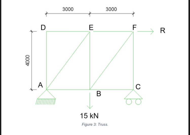
Question: A truss shown in Figure 3 below has pin support at Joint A and a roller at Joint C . If Joint B is subjected
A truss shown in Figure below has pin support at Joint A and a roller at Joint C If Joint is subjected to a point load of
Calculate the force Fw in the members due to loading
Calculate force Fp in all members
Tabulate and calculate Fw Fp L
Calculate the unknown load R at joint F that can be applied without causing deflection Figure : Truss.
Figure : Truss.
Step by Step Solution
There are 3 Steps involved in it
1 Expert Approved Answer
Step: 1 Unlock

Question Has Been Solved by an Expert!
Get step-by-step solutions from verified subject matter experts
Step: 2 Unlock
Step: 3 Unlock