

Question: A truss structure shown below is pin supported at joint L and roller supported at joint I. The reactions of these supports due to the
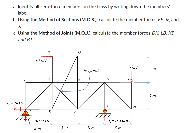
A truss structure shown below is pin supported at jointL and roller supported at joint I. The reactions of these supports due to the applied forces at joints C and G have been calculated and presented in the figure below.
Identify all zeroforce members on the truss by writing down the members label.
Usingthe Method of Sections MOS calculate the member forces EF JF and JI
Usingthe Method of Joints MOJ calculate the member forces DK LB KB and BJ a Identify all zeroforce members on the truss by writing down the members' label.
b Using the Method of Sections MOS calculate the member forces EF JF and JI
c Using the Method of Joints MOJ calculate the member forces D K L B K B and B mathrm~J
Step by Step Solution
There are 3 Steps involved in it
1 Expert Approved Answer
Step: 1 Unlock

Question Has Been Solved by an Expert!
Get step-by-step solutions from verified subject matter experts
Step: 2 Unlock
Step: 3 Unlock