

Question: Need the forces computed for members 18,19,22&23 . . . The pedestrian bridge which was under construction at the International University of Florida collapsed during
Need the forces computed for members 18,19,22&23.
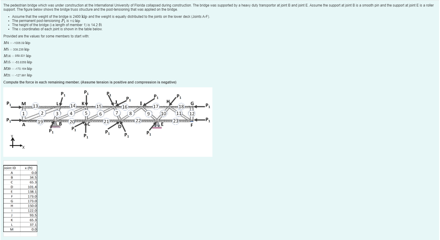
. . The pedestrian bridge which was under construction at the International University of Florida collapsed during construction. The bridge was supported by a heavy duty transportor at joint B and joint E. Assume the support at joint B is a smooth pin and the support at joint E is a roller support. The figure below shows the bridge truss structure and the post-tensioning that was applied on the bridge. Assume that the weight of the bridge is 2400 kip and the weight is equally distributed to the joints on the lower deck (Joints A-F). The permanent post-tensioning Pis 112 kip The height of the bridge (1.e.length of member 1) is 14.2 ft The x coordinates of each joint is shown in the table below. Provided are the values for some members to start with: M4 =-1006.09 kip M5 = 300.236 kip M14 =859.831 kip M15=-53.8358 kip M20 =-170.184 kip M21 = -127.991 kip Compute the force in each remaining member. (Assume tension is positive and compression is negative) P1 P1 P1 P1 P1 M L KV G 15 16 -17 P 13 2 2 14 4 1 3 5 6 7 8 9 18 10 11 23 E 12 P1 19 21 22 -P1 B 20 P1 40 D F P1 P1 P1 P1 Joint ID A B B C D D E F G H 1 x (ft) 0.01 34.5 65.3 101 101.4 138.1 172 173.0 173.0 150.0 122.0 93.5 65.3 37.1 0.0 K L M . . The pedestrian bridge which was under construction at the International University of Florida collapsed during construction. The bridge was supported by a heavy duty transportor at joint B and joint E. Assume the support at joint B is a smooth pin and the support at joint E is a roller support. The figure below shows the bridge truss structure and the post-tensioning that was applied on the bridge. Assume that the weight of the bridge is 2400 kip and the weight is equally distributed to the joints on the lower deck (Joints A-F). The permanent post-tensioning Pis 112 kip The height of the bridge (1.e.length of member 1) is 14.2 ft The x coordinates of each joint is shown in the table below. Provided are the values for some members to start with: M4 =-1006.09 kip M5 = 300.236 kip M14 =859.831 kip M15=-53.8358 kip M20 =-170.184 kip M21 = -127.991 kip Compute the force in each remaining member. (Assume tension is positive and compression is negative) P1 P1 P1 P1 P1 M L KV G 15 16 -17 P 13 2 2 14 4 1 3 5 6 7 8 9 18 10 11 23 E 12 P1 19 21 22 -P1 B 20 P1 40 D F P1 P1 P1 P1 Joint ID A B B C D D E F G H 1 x (ft) 0.01 34.5 65.3 101 101.4 138.1 172 173.0 173.0 150.0 122.0 93.5 65.3 37.1 0.0 K L M
Step by Step Solution
There are 3 Steps involved in it

Get step-by-step solutions from verified subject matter experts